 |
CCP4 Molecular Graphics Documentation |
 |
| Picture Definition Files |
Introduction
Picture definition files are human readable and editable files which define the scene displayed by CCP4mg; status files can also be used to save the scene information but these are not human readable. The information in the picture definition file corresponds to that presented in various interface windows:
| Picture definition objects | User interface equivalent |
| Data objects (MolData, MapData etc.) | The display table |
| Display objects (MolDisp, MapDisp etc.) | The display table |
| SelectionScheme | Selection menu: Save current selection |
| ColourScheme | Colour menu: Edit colour scheme |
| ParamsManager | Preferences |
| Colours | Preferences: Display: Colours |
| View | The view - usually controlled by mouse input |
| Wizard | A picture wizard scene |
| Inline data | A coordinate file |
An important use of picture definition files is by non-graphical programs which use a picture definition file to define some graphical information to present to users in CCP4mg. Another use may be if you have set up a complicated picture for one molecule and then want to do the same, or a similar picture, for another molecule; in this case it may be quicker to write out and edit a picture definition file than it would be to set up the picture again in the display table. But it may be even quicker to use the Display same as option on the model icon menu.
If you need to create a picture definition file the easiest way is to set up the display table as you would like it and then save a picture definition file which can be edited to the exact form that you require.
Picture definition files can be saved or read from the Picture definition files option on the Tools pull-down menu. The Save picture definition option will save the current display to a file. In the file selection window is an option Only save non-default parameters which is on by default and means that the minimum of information about each object in the display is saved. The appearance of the display is also affected by some of the program Preferences such as the Model Drawing Style - these will also be saved to the file if they are selected in the Save options interface (accessed from the Picture definition files sub-menu).
On reading a picture definition file there are options to Keep currently loaded data and to Hide slow-to-draw objects such as surfaces
CCP4mg can be started with a command line option which loads the picture definition file:
ccp4mg -picture filename.mgpic.py
File->Restore can also be used to load a file into a running CCP4mg.
Also a picture definition file can be saved, by File->Save status to file. The file type should
be changed to "Editable picture definition file".
File Format
The picture definition file is a simple Python script. There are several benefits to using Python here:
- The Python parser is totally reliable and gives good error messages
- If you, the user, must learn a file format it might as well be something which could be more generally useful
- The scripting language has built-in flow control commands
- In future, additional functionality could be made accessible via the picture definition language
There is a quick introduction to Python here.
Here is a short example of a picture definition file which can recreate the picture:
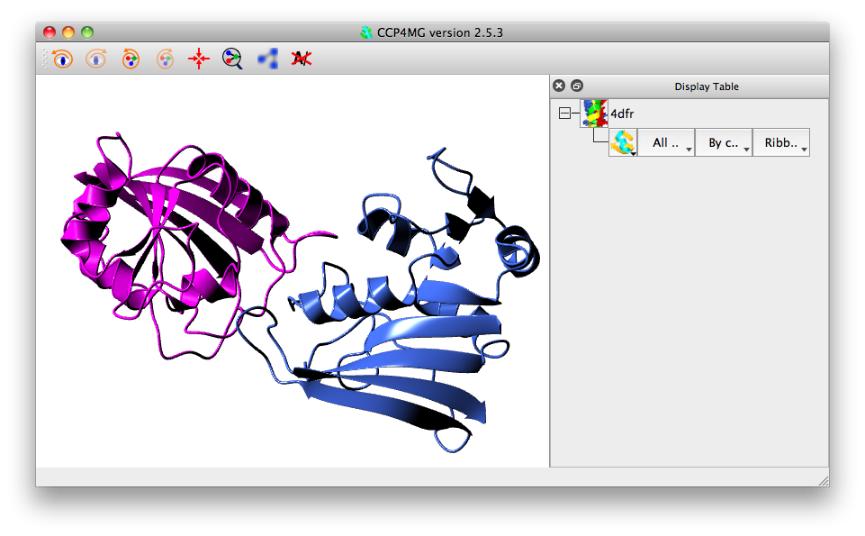
MolData (
     filename = ['FULLPATH', '3gcp.pdb', '/richelieu/stuart/ccp4mg_tutorial/3gcb.pdb']
      )

MolDisp (
          selection_parameters =  { 'select' : 'all'},
          colour_parameters =  { 'colour_mode' : 'bychain'},
          style_parameters =  { 'style_mode' : 'SPLINE'  }
        )
Two objects are defined in this file (in strict Python terminology these are two instances of a class, see Python classes), and these correspond to the two lines in the display table. The two objects are:
- A MolData object is the data object corresponding to a model coordinate file. This has one attribute: the coordinate file filename (the syntax for this is explained later). It could have additional attributes, for example, to define symmetry mates or a transformation to apply to the coordinates.
- A MolDisp display object defines how the MolData object is displayed. This has attributes: selection_parameters, colour_parameters and style_parameters and could have additional attributes, for example, to define atom labels.
This file contains sufficient information to recreate the picture above. When the script is read it does not directly create the data and display objects but creates shadow objects which just hold the description of the object. If there are no problems reading the script then the information in the shadow objects is used to create the real MolData and MolDisp objects. This approach should help prevent faulty script files from corrupting the program.
This script relies on the program assuming that a display object belongs to the preceding data object. The connections between data objects and display objects can be made explicit as explained later.
Data Objects
The key information for any data object is the filename of the data file.
filename = ['demo', '2ins.pdb', '/home/lizp/demo_data/2ins.pdb']
The format for the file name is a list (Python list syntax) with three items:
- CCP4i project directory name (or the word 'FULLPATH' if the file is not in a project directory)
- file name (without the directory component)
- full pathname of the file
When reading a file CCP4mg first tries looking in the project directory for a file with the file name; if this does not exist it will try using the full pathname.
All data and display objects have a name which is a one-word text string that is used to reference the object. A data object name is usually derived from the name of the data file with the directory path and file extension stripped off. For the example above the data object name would be '2ins'. If there are multiple data objects with the same filename attribute then the second and subsequent objects are named filename1, filename2 etc.. The name of an object can be set explicitly, for example:
MolData (
     name = 'molecule_1',
     filename = ['demo', '2ins.pdb', '/home/lizp/demo_data/2ins.pdb']
      )
sets the name of the MolData object to 'molecule_1'.
Display Objects
If a data object is defined without any display objects then one display object with default attributes is created. Any display object attribute not defined in the script will be given a default value.
All display objects have three key attributes which are those controlled by the widgets in the three columns in the display table. The program always writes these attributes to the picture definition file. Additional attributes which are controlled from the icon menu in the display table are usually only written to the script if they have non-default values. Some properties of display objects, such as a font, are too complex to be described by a single parameter and so multiple parameters are grouped together in a Python data structure called a dictionary, for example in defining annotation:
Annotation (
             font =  {  'weight' : 'bold',
                        'slant' : 'i',
                        'family' : 'utopia',
                        'size' : '14'  },
             colour = 'complement',
             selection = 'This is annotation <br>',
             position = [11.52, 11.81, 15.56]          )
the font attribute is a dictionary with keys: weight,slant,family and size.
Theselection_parameters attribute is a selection rule which defines the required atoms. For example a display object that displays the Calpha trace and two ligands
MolDisp (
          colour_parameters =  { 'colour_mode' : 'atomtype'},
          style_parameters =  {
                         'style_mode' : 'BONDS'  },
          selection_parameters =  {
                         'select' : 'cid',
                         'cid' : 'catrace or //500(NDP) or //501(MTX)',
                         'monomers' : ['//500(NDP)', '//501(MTX)']  } )
SelectionScheme Objects
This creates a named selection which is equivalent to that created by the Save current selection on the display table selection menus. For example:
SelectionScheme (
          name = 'interesting_residues',
          context = '1df7',
          selection = '/1/A/10-20 or //500(NDP) or //501(MTX)',
          )
The attributes are
name a one-word name for the scheme
context is either 'generic' or the name of a MolData object. If the attribute is not given then the SelectionScheme is assumed to be associated with the preceding MolData object.
selection which is a selection command
When writing a picture definition file CCP4mg will write out generic SelectionSchemes that are currently used by a display object and all SelectionSchemes associated with a MolData object. Note that SelectionSchemes are also automatically saved to model definition files but the definition imported from the picture definition file will override any in the model definition file with the same name.
The pre-defined SelectionScheme can be used by a display object:
MolDisp (
          selection_parameters = {
                             'select' : 'selection_scheme',
                             'selection_scheme' : 'interesting_residues' },
          style_parameters =  { 'style_mode' : 'SPHERES'  },
          colour_parameters =  {
                         'colour_mode' : 'rules',
                         'user_scheme' : ['c_grey','1df7' ] }
        )
In this example the selection_parameters for the display object have select set to 'selection_scheme' to indicate using a SelectionScheme and selection_scheme gives the name of the SelectionScheme.
ColourScheme Objects
ColourScheme objects work in similar fashion to the SelectionScheme objects but they create a named colour scheme which is equivalent to saving a colour scheme from the Edit colour scheme option on the model display colour menu. An example of defining a ColourScheme:
ColourScheme (
          name = 'c_grey',
          context = 'generic',
          colours = [['green', 'all'],
                     ['grey', '/*/*/*/*[C]:*'],
                     ['red', '/*/*/*/*[O]:*'],
                     ['blue', '/*/*/*/*[N]:*'],
                     ['yellow', '/*/*/*/*[S]:*'],
                     ['tan', '/*/*/*/*[H]:*'],
                     ['magenta', '/*/*/*/*[P]:*']] )
The ColourScheme attributes are:
name a one-word name for the scheme
context is either 'generic' or the name of a MolData object. If this attribute is not given then the ColourScheme is assumed to be associated with the preceding MolData object.
colours is a list of colouring rules; each rule is a list of two elements; the first element is a colour name and the second is a selection command. For each rule the atoms selected by a selection command are given the associated colour and the rules are applied in the order they are given - colouring by a later rule can override a preceding rule.
Note that ColourSchemes are also automatically saved to model definition files but the definition imported from a picture definition file will override any in the model definition file with the same name.
The pre-defined ColourScheme can be used by a display object:
MolDisp (
          selection_parameters = {
                             'select' : 'selection_scheme',
                             'selection_scheme' : 'interesting_residues' },
          style_parameters =  { 'style_mode' : 'SPHERES'  },
          colour_parameters =  {
                         'colour_mode' : 'rules',
                         'user_scheme' : ['c_grey','1df7' ] }
        )
In this example the colour_parameters for the display object have colour_mode set to 'rules' to indicate using a ColourScheme and user_scheme gives the name of the ColourScheme which is a list of two elements; the first element is the ColourScheme name and the second is the name of the model data object that the ColourScheme is associated with.
ParamsManager Objects
The ParamsManager object is used to hold various user preferences. The most useful preferences are probably those for the model drawing style which corresponds to the preferences for Drawing style in the Model display folder or, for individual display objects, Molecule drawing style.. on the display object icon menu. An example of the picture definition format:
ParamsManager(
          name = 'model_drawing_style',
          arrow_width = 1.2,
          flatten_loop = 1,
          helix_style = 1,
          worm_width = 0.3,
          ribbon_style = 1,
          alpha_helix_width = 1.0          )
Note that the ParamsManager does not need to have all the parameters associated with that type ParamsManager defined; any missing parameters will take default values. The ParamsManager must have a name parameter which indicates the type of data contained. The generic model drawing style is called 'model_drawing_style' and customised drawing styles for individual display objects should be called something like 'model_drawing_style_xxxx'. This is associated with the display object by the drawing-style parameter of the display object. For example:
MolDisp (
          selection_parameters = { 'select':'cid', 'cid': 'A/' },
          colour_parameters =  { 'colour_mode' : 'secstr' },
          style_parameters =  { 'style_mode' : 'SPLINE' },
          drawing_style = 'model_drawing_style_my_ribbon'
        )

ParamsManager(
          name = 'model_drawing_style_my_ribbon',
          arrow_width = 1.2,
          flatten_loop = 1,
          helix_style = 1,
          worm_width = 0.3,
          ribbon_style = 1,
          alpha_helix_width = 1.0          )
The Colours Object
This corresponds to the Preferences option Colours in the Display folder. An example of a picture definition Colours object:
Colours (
   colour_definitions = [
         ['white', [0.0, 0.0, 0.0, 1.0]],
         ['olive', [0.4, 0.6, 0, 1.0]]] ] )
This redefines white (to be black) and defines a new colour, 'olive'. The format of input is that Colours has an attribute colour_definitions which should be a list of colour definitions where each element of the list is another list with two elements. The first element is a text string which is the name of the colour and the second element is another list of four floating point numbers which are the RGB values (as values in the range 0.0 to 1.0) and an 'alpha' value which should be 1.0. For explanation of RGB see Wikipedia.
Wizard Objects
An alternative approach to specifying display objects is to specify a Picture Wizard script to be used to generate the display objects automatically. There is a library of Picture Wizard scripts or you can create your own. Most scripts will work without any additional input; some take optional input, usually of atom selections, and some scripts require atom selection input. The scripts absolutely requiring some selection input are those for displaying interfaces where two sets of atoms must be defined. An example of using A Wizard object:
MolData (
       filename = ['FULLPATH', '1gtf.pdb', '/richelieu/stuart/ccp4mg_tutorial/1gtf.pdb']
      )

Wizard ( drawing_style = 'interfaces:residues',
    range1 = '/1/A',
    range2 =  '/1/B'
       )
The Wizard object is immediately after the MolData object that it will be applied to. Wizard objects should always have a drawing_style parameter which is the Picture Wizard folder and the script name separated by a colon. The most common additional parameters are rangen or ligandn which specify sets of atoms. The allowed parameters for each template are shown in the template file in the CHOICES section.
Inline Objects - Including Data in the File
This is a mechanism for including data in a picture definition file. It has currently only been tested for including PDB coordinate file data. An example of defining an inline object:
Inline (name =  'pisa_t1.pdb' , data = '''
ATOM      3  N   VAL D   2      14.250  10.141  -6.104  1.00 45.00           N
ATOM      3  CA  VAL D   2      15.003  10.746  -7.205  1.00 45.00           C
ATOM      3  C   VAL D   2      14.112  10.940  -8.441  1.00 30.52           C
ATOM      3  O   VAL D   2      13.430  11.963  -8.554  1.00 45.00           O
ATOM      2  CB  VAL D   2      16.311  10.009  -7.532  1.00 32.25           C
ATOM      2  CG1 VAL D   2      16.034   8.920  -8.586  1.00 25.32           C
ATOM      3  CG2 VAL D   2      17.343  11.002  -8.105  1.00 45.00           C
ATOM      1  N   ASN D   3      14.095   9.983  -9.372  1.00 20.04           N
ATOM      3  CA  ASN D   3      13.227  10.230 -10.540  1.00 45.00           C
....

ATOM      6  ND2 ASN C  21      -2.497  21.308   3.598  1.00 36.48           N
ATOM      5  OXT ASN C  21       1.431  24.714   2.915  1.00 45.00           O
''' )
The data will be written to another data file called name and placed in the users current project directory. Any MolData object that needs to reference that file should have define the filename in the form:
MolData (
     filename = ['INLINE', 'pisa_t1.pdb', '']
      )
The word INLINE is used instead of any project or path.
Lighting parameters
The OpenGL lighting parameters are also saved in to the picture definition file. The syntax is as below:
ParamsManager(
     name = 'light_params',

     lights =  {
                    '0' :  {
                                   'position' : [
                                                  15,
                                                  1,
                                                  34.0 ],
                                   'on' : 1,
                                   'specular' : (0.76999998092651367, 0.76999998092651367, 0.76999998092651367, 1.0),
                                   'diffuse' : (0.40999999642372131, 0.40999999642372131, 0.40999999642372131, 1.0),
                                   'ambient' : (0.11999999731779099, 0.11999999731779099, 0.11999999731779099, 1.0)  }  },
     nLights = 1
)
There is an entry lights which is a Python dictionary containing an entry '0','1','2', ...
for each light depending on the number of lights (normally a maximum of 8).
(There is also an entry nLights for hisorical reasons).
Each light contains a position entry with x,y,z coordinates, an 'on' entry and the information about the lights
ambient specular and diffuse properties. Please refer to OpenGL documentation for explanation of these properties.
The View Object
The view object defines the centre of the screen, the view orientation and the zoom, for example:
View (
     centre_xyz = [-6.78, -17.32, -0.62],
     zoom = 0.51,
     orientation = [0.572, 0.209, -0.517, 0.599]     )
The centre_xyz is the coordinates to appear at the centre of the screen. An alternative way to specify the screen centre is by selecting a model and, optionally, some atom(s) in the model. For example:
View (
     centre_MolData= '1abc',
     centre_selection = '//A/27',
     zoom = 0.51,
     orientation = [0.572, 0.209, -0.517, 0.599]     )
The centre_MolData attribute is the name of the model. centre_selection is optional and is a selection command.
The orientation is represented as a quaternion. The zoom and orientation are not easy to generate outside of molecular graphics.