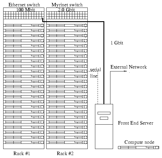
A typical configuration for a system is shown in figure 1.
The system consists of one or more racks containing the compute nodes.
These are connected via fast ethernet. A front end server is connected to
the ethernet switch via a 1 Gbit port allowing the compute nodes high
speed access to network services such as NFS (Network File System) on the
front end server. Optionally you may have a Myrinet network connecting
the compute nodes via a Myrinet switch. A serial network is also be available
for console logins should the other networking fail. If you have
not purchased a serial port switch a single serial cable will be provided
so that you can access any compute node from the front end server
in case of an ethernet failure (see the System Administration chapter for
details).
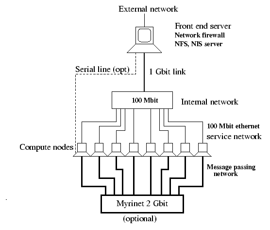
Figure 2. shows a typical network arrangement (8 compute nodes). Note that on the systems with Myrinet, the Myrinet networking only connects the compute nodes. When a parallel job is launched from the front end it is first broadcast to the compute nodes via the 1Gbit link and the 100 Mbit network.