To make things much easier for both the users of the bulletin board and us writing this newsletter, members who ask questions or instigate discussions on the board are now asked (urged!) to post a summary of all the reactions received, whether on or off the board.
For each subject below, the original question is given in italics, followed by a summary of the responses sent to CCP4BB (together with some additional material). For the sake of clarity and brevity, I have paraphrased the responses, and all inaccuracies are therefore mine. To avoid misrepresenting people's opinions or causing embarrassment, I try not to identify anyone involved: those that are interested in the full discussion can view the original messages (see the CCP4BB archive).These summaries are not complete, since many responses go directly to the person asking the question. While we understand the reasons for this, we would encourage people to share their knowledge on CCP4BB, and also would be happy to see summaries produced by the original inquirer. While CCP4BB is obviously alive and well, we think there is still some way to go before the level of traffic becomes inconvenient.
Thanks to all the users who are now dutifully posting summaries.
|
- Refmac, ARP/wARP and TLS
- Refmac vs. ...
- Refinement weights
- Refmac FOM
- The monomer libraries
- Modified amino acids in Refmac5
- Using new library in Refmac5
- LINK statement
- Mon-lib problem when using ARP/WARP 6.0 (CCP4i)
- Treatment of oxidized Cys in Refmac
- What is the CCP4 (refmac5) equivalent of an omit map? and: do lower Rfactors after TLS refinement reflect a better model?
- Overlapping in Refmac
- Overlapping ligands
- Overlapping TLS groups in Refmac5 and TLSANAL?
- REFMAC vs. CNS SigmaA maps
- ARP/wARP Mode Solvent
- Refmac and prior phase information
- R factors from refmac and sfcheck
- Non-crystallographic symmetry
- Nonx restraints on split residues (Refmac5)
- NCS in Refmac5 - troublesome zinc
- Problem in MAKE_U_POSITIVE
- TLS refinement
- TLS refinement - which tls file to use in subsequent cycles
- TLS refinement - how to describe the TLS groups
- TLS refinement and structure deposition
- TLS refinement - 'actual' and 'residual' Bfactors
- TLS refinement: Fix B-factors?
- Is it possible to write out Fc_solvent and Fc_TLS in REFMAC?
- Nucleic acids and alternate conformations within a strand: refmac5
- REFMAC5 maximum likelihood refinement
- mmCIF dictionary to SMILES?
- Bulk solvent model in REFMAC
- Mosaicity - high and low
- Problems with low mosaicity crystals
- Data reduction for mosaic crystals
- Twinning
- Non-merohedral twinning
- Non-merohedral twinning - how do I determine if it is?
- Perfect twinning
- Please teach about twinning
- Twin problem
- Various
- Multi-channel pipettors for crystallization
- Pksearch
- Archeal protein expression in E. coli
- Unusually high solvent content
- Poly A to Poly S
- Anisotropic B-factors
- MIR-test case
- A simple question of resolution
- Docking programs
- Dry shipper
- Cross-platform NIS
- Mapstretch; also: fitting atomic models into cryoEM maps
- Side Chain Assignment of more-or-less unknown protein
- Indexing problem
- Molecular Replacement woes!
- Structure-based sequence alignment
- Examples of pH affecting ligand conformation
- Selenomethionine prep
- PC crystallography
- CNS composite SA omit
- A SAD case
- PEG 550 MME as cryoprotectant
- Riding hydrogens
- PDB2CIF/CIF2PDB
- Strange NCS/refinement problem
- AMoRe Rotation Function Scoring
- Diffraction images to gif/jpg
- CCP4 - Pentium 4
- Radiation damage
- Structure question - how long is a 9-residue peptide?
- Announcements, software releases and special places on the www
- Clipper
- SHARP/autoSHARP
- PARVATI
- povscript+
- MAPMAN server
- Gerard's Reprint Mailer
- New version of PDB-mode for Xemacs/Emacs
- Mosflm
- Uppsala Electron Density Server
- PRODRG, HICUP wrt CNS parameters
- Raster3D Version 2.6e
- ccp4get CCP4 auto-installer
- EBI-MSD group services
- ARP/wARP version 6
- HIC-Update release 6.1
- Reminder X-ray generators can bite
- PyMOL
- AMoRe webpage
|
(January 2002)
I refined my structure using Refmac5 and CNS using the same set of Rtest reflections. Always, Refmac5 gave a lower R-factor compared to CNS using max likelyhood refinement. Has anybody else noticed this? Why would this occur?
I am sure we would like to say that this was because refmac is better - and of course it is.. BUT the R factor within a few decimal places you get is very much a function of your scaling algorithm and at low resolution the two can differ quite a lot....
Just for comparison - do you have resolution? did you use bulk solvent? TLS? etc etc..
Usually good indicator is behaviour. I.e. difference between initial and final values. To confirm the above: scalings are different.
At that point a question was added to this thread:
I am very interested in this comparison too. Can anybody give me some details about the comparison between Refmac5 and CNS? I have never used Refmac5 before. Can refmac5 do simulated annealing?
Can some-one comment on how valuable simulated annealing is at various resolutions?
In examples at better than 2.5Å we usually seem to finish up doing just about the same amount of rebuilding as you do after a ML run.
At resolutions better than ~2.0Å there is not doubt in my personal (and slightly biased, see also Warren/PyMol) opinion that ARP/wARP with Refmac(5) will outperform simulated annealing in CNS (or Refmac-on-its-own). It takes (significantly) longer, but no longer than a few hours that can be used for coffee/beer/sleep/more-hard-work (use the last option carefully, it can be bad for you). Most of the rebuilding can be eliminated by doing the autobuilding which will create a very good model (nearly perfect really) for the bits that it does build - lets say 80-95% of the structure. You have to do the rest on your own.
And as a reminder there IS in ARP/wARP 5.1 a script/program to build and real-space refine side chains as well - most people seem to ignore that (there are at least two ActaD papers that explicitely state that 'ARP/wARP does not build side chains' !!!).
I am not 100% convinced of what to say for 2.2 - 3.2Å. There have definitely been cases that ARP/wARP with Refmac has produced at that resolution range (even at 3.2Å, but with high solvent content) MAPS that were far better than various tries with CNS and simulated annealing. Especially when starting from incomplete models. HOWEVER, CNS produced the BETTER model ! (ARP/wARP will throw away atoms it does not like so the model is BAD !) Thus I would suggest to get the map with ARP/wARP - REFMAC and the model either from refmac(5) alone (for resolutions not much worse than ~2.7Å) or from CNS (especially if resolution is worse than ~2.7Å).
Initially, I was very enthusiastic when simulated annealing was introduced in macromolecular refinement. My enthusiasm quickly turned into skepticism, when in several projects with resolutions ranging from 1.7 to 2.5Å I looked both at the resulting structures and the electron density maps: I had to go through the whole structure again to correct all these little errors (side chain and main chain) that simulated annealing obviously has introduced; the electron density maps showed a lot of model bias, i.e. too-good-to-be-true density around the "refined" model, and virtually flat density for the missing parts. Thus, simulated annealing heavily over-fitted my structures, which was presumably the reason for the introduction of the concept of the Free-R factor and the use of multiple simulated annealing rounds with averaged electron density maps. I also tried the combination of torsion angle dynamics with maximum likelihood target, and it seems to give good composite-omit-maps, but apart from that, I don't see any real advantage over careful inspection of electron density (omit) maps and fitting by hand. Some people think, that it might still be very useful when the resolution is low (say, around 3Å), and if your model is a beta-strand with many short side chains (Ser, Thr, Val, Asx) that have to flip around simultaneously along with a slight shift in the main chain. But at that resolution, model bias is a very serious problem and it will be difficult to judge the results. At high resolution, simulated annealing should work very well, but there are more efficient algorithms available (ARP/wARP, for instance).
To summarize, my personal verdict is that simulated annealing in macromolecular refinement is a heavily overestimated technique.
Since there seems to be little defense of CNS in this debate, I thought I'd give my two cents worth. First, there is no doubt that both ARP/wARP and REFMAC are superb programs. However, many statements in this debate are of questionable validity. First, CNS (and earlier, XPLOR) were developed to address difficult refinement problems at low to moderate resolution (i.e. when data are very limited). So, to claim that simulated annealing is best suited for higher resolution refinements is untrue and misses the declared purpose of the approach - to minimize the probability of a poor initial model being trapped in a local minimum when there are not enough data to guide the refinement to the global minimum. This does not mean that you will never have to manually correct the resulting model, or to adjust the starting temperature for the refinement. It does mean that you don't have to rely solely on manual rebuilding to correct potentially major errors in an initial model that has been built into poor maps. The value of simulated annealing for this purpose has been extensively studied and documented in the literature. In addition, the combination of torsion angle refinement and simulated annealing optimization reduces the dimensionality of the search space approximately 10-fold, vastly decreasing the risk of overfitting by eliminating bond angles and lengths as refineable parameters. If you have data in the 3.5 to 2.5 Å range, you have no hope of fitting these model parameters meaningfully, no matter how tightly they are restrained, and it is proper refinement practice to not fit them at all.
Secondly, the Free R was not introduced as a stopgap measure to correct for problems in simulated annealing refinement. It was introduced because reporting a conventional R value as an indicator of model quality is at best naive and at worst willfully deceptive. Again, this has been extensively documented in the literature.
In summary, a direct comparison of REFMAC-ARP/wARP and CNS is complex, and should include a more careful consideration of the type of refinement being performed, the amount of data available, and the reliability of the initial model. A collection of anecdotes about how these programs compare in a handful of refinements does not add meaningfully to a proper assessment of their worth.
A historical perspective...
Simulated annealling was quite the rage in the late 1980's. At that time, most electron density maps were fit by someone who had never fit an electron density map (i.e. a student or post doc doing their very first map). The map-fitting programs had neither rotamer libraries, nor fragments of main chain, nor any database automation that could be used as a tool. Thus, I believe many coordinates initially were fit rather badly without regard to stereochemistry. We needed a good refinement program with a large radius of convergence to get atoms into the right position. X-PLOR fulfilled that need.
Nowadays, with the tools provided by fitting programs and the knowledge of our predecessors, fewer mistakes are made in the early interpretation stages and those that are made are often discovered quickly. Thus, there is less need for simulated annealing to get out of false minimums.
I'm still favouring CNS for conventional maximum likelihood refinement: it is very fast and produces both excellent models and electron density maps. And it has the better bulk solvent correction due to the missing solvent B-factor in the mask approach of REFMAC.
While one can continue work on the relative merits of CNS vs. REFMAC, I think I will focus on what I miss in ARP/wARP-REFMAC. ARP/wARP is terrible at using NCS. If you are working with multimeric proteins and at medium resolutions around 2.5Å, CNS - strict NCS works miracles. While I can definitely use REFMAC to refine, 'dm' to average, and manually build one model and generate the next etc.. would it not be great if ARP/wARP could do it. Few people will dispute that 4 fold averaging at 2.5Å produces better maps than no averaging at ~2.0Å. CNS, simulated annealing and water picking do an absoltely wonderful job with strict NCS.
I would disagree only partially. ARP/wARP does not do a terrible job with NCS. It does NOTHING with it, it just disregards it.
Otherwise you are right! It would be great to use NCS!
Since torsional MD became stylish I have been unable to make it run properly, since I didn't have whatever parameter file it wanted for haem. Somehow I managed to survive without it.
And from the same contributor:
I am not entirely satisfied with NCS under CNS. You have a choice between strict NCS (constraints) or NCS restraints. If you want to switch from one to the other, you have to build a new coordinates file and then re-run generate. This is a nuisance. And in both cases, the NCS is constrained/restrained by the NCS matrix, which itself is not refined. To do that, you have to build the whole multimer and put it through rigid body fitting. Why not allow the NCS matrix to be refined with either/or constraints & restraints?
And to bring in a dark horse, SHELX has a different approach to NCS which makes a lot of sense to me. NCS restraints are applied not to the position as defined by the NCS matrix, but by extra restraints on torsional angles. This is particularly appropriate for structures with hinges or other localized differences between monomers.
I pretty much shudder at my late 80's low R-factors which I annealed. I am sure CD will do me one day (but hey I deposited the data). See the original message, with a script for ARP-REFMAC (re)cycling.
I know that the real question everyone is dying to have answered is: "How many levels of recursion can you embed in a CNS or RefMac command file?" See the original message for a (almost ?!) balanced argument.
Simulated annealing looks very attractive from a theoretical as well as practical point of view so I tried it many times using default protocols and all kinds of variations. I never was happy about the result. I kept trying because it looked like it should work but still without any real success stories. These were 2.2 to 2.8 Angstrom resolution structures. My feeling is that simulated annealing always causes damage to your model in addition to improvements. The more accurate the model, the less improvements (simulated annealing) can be made but there is still the damage. See the original message for a full set of reasons why this person is using one or the other.
I still think, that TNT (5F) is one of the most elegant and transparent refinement packages if it only had a good implementation of the maximum likelihood target (the one from Navraj Pannu works in principle but it didn't write out sigmaa-weighted electron density maps; BUSTER/TNT is an attractive alternative, but it is still in the development phase). See the original message for more.
From my personal experience and from working with other CNX users on their problems comparing performance of the different programs is a valuable and productive way to learn when and how these programs can be applied. In fact, X-PLOR/CNS/CNX and REFMAC-ARP/wARP can be quite complimentary to each other depending on model quality, the amount and accuracy of X-ray data available and type of refinement. As has already been stated, ARP/wARP works the best with high resolution data, I have seen CNS/CNX do an excellent job with data in the (3.5-2.2) Å range, particularly when a starting protein model is relatively crude. In many cases loops can move more than 2Å to their correct positions and side-chains are correctly placed into the density.
Another advantage that X-PLOR/CNS/CNX provides is the ability to write/merge various task files in order to make your own refinement protocols. To summarize, a direct comparison of REFMAC-ARP/wARP and X-PLOR/CNS/CNX should not focus on which program is better or worse but rather how one can benefit from using many programs with different data.
A related question:
I'd be interested in people's humble opinions on their experiences with nucleic acids in particular. Many of the backbone torsion angles aren't well defined in moderate-resolution maps (2.5ish), but they do matter. Especially for non-canonical structures, I've wondered if we're really dealing with them properly.
The word is that XPLOR/CNS is far better than REFMAC on refining nucleic acids. REFMAC (.. and PROLSQ back then) make the sugar backbone 'funny' according to some, the bases non-planar according to others. Partially true - I think. See the original message for a more up-to-date word.
Well, IMVHO (V stands for Very) "partially" is the good adverb here. It was not the case for me: Refmac (at that time it was Refmac4/Protin) did a very good job with my DNA structure. See the original message for the full picture, and then some on SHELXL!.
As far as I can see, it is always wrong to restrain ring-puckers in sugar rings. See the original message for an explanation of this bold statement. This also answers a question posed a few weeks later: Is there any way of restraining the sugar puckers of nucleic acid residues during refinement in REFMAC (I am using version 5.1.09 with TLS refinement)?
Then, a long time coming...:
To enhance the (bio)diversity of this fight: how about SHELXL for high-resolution data?
And, again, a number of weeks later by someone else:
Has anyone had experiences of refining ultra-high (better that 1.0Å) resolution structures with refmac5 and SHELXL? How did they compare?
But no answers to those questions...
A question about not-so-high-resolution and the performance of SHELX:
I was able to fit the AA into the solvent-flipped density map from CNS -
everything looks just wonderful except for one five-residue loop. However,
SHELXL refinement does not like this model, returning R(free) around 50%
at 1.8Å resolution. Any suggestions, anyone? Thanks very much!
BTW, does this have anything to do with these two facts: 1) the space
group is I432; and 2) the model is being refined against Se-Met data
without merging Friedel mates?
SHELXL isn't very happy at 1.8Å - why not use REFMAC or CNS - both faster and more appropriate at this resolution?
I feel I must take exception -- at least, with the first part of that statement: SHELXL does a rather good job even at 3Å, particularly with geometries. But I can't argue with the 'faster' thing... lest this degenerate into a flame war ;-)
As to why SHELXL craps out... hard to tell, it could be anything: mistakes in the ins file (are you sure your HKLF is correct), wrong formatting of the hkl colums... those are the more brain-dead ones, try the SHELX FAQs: SHELX FAQ macromolecules and Thomas Schneider's SHELXL FAQ.
(January 2002)
While we're on the subject of refinement, with REFMAC, CNS, TNT, and
SHELX, what do people do to adjust the relative weights.
In CNS I typically refine with "wa=-1", which sets up a reasonable
relative weight between the geometry terms and the xray terms for an
incomplete model. Towards the end of refinement, I double or triple
the value found with "wa=-1". I've found that with "wa=-1" various
programs like WHATCHECK and PROCHECK find that the restraints are too
tight. When I increase wa, then both the R(cryst) and R(free) decrease a
bit; at some point R(free) doesn't drop anymore, even if R(cryst) does, so
that's a reasonable place to stop. I also look at the rmsd on bond
lengths (0.01 or lower as a target), and on bond angles (1.5 or lower as a
target).
In SHELX, I leave the weight as 0.2, and never mess with it, even with
small molecule structures. The sigma's of the intensities seem to be
correct from various packages (DENZO, bioteX, MOSFLM), since the small
molecule structures gives GOF's close to 1.0 without the additional fudge
(weight adjustment) in SHELX. Since I don't know what the systematic
errors are in the model or the data, I don't believe that the GOF's should
be close to 1.0, unless you know you have excellent data and an excellent
model.
I haven't used REFMAC or TNT in awhile, so I'm not sure how the weighting
schemes are adjusted.
In my experience I get very good results in all different refinement programs when I set the relative weights such that the final rmsd for bond lengths is about 0.012-0.015Å and the rmsd for bond angles is around 1.5-2.0 degrees. Regarding the doubling of the wa in CNS: if you look at the scalenbulk module, which determines that weight, the refined wa is divided by a factor of 2. This factor was introduced later (as Paul Adams told me), but I always remove it, because otherwise CNS refines the model with, in my experience, too tightly restrained geometry.
In REFMAC use the command "WEIG EXPE MATR" followed by a value that has to be lower for tighter geometry. I usually end up with values around "0.5".
I suspect this is the factor two that goes back to the early days of Rfree, when many people playing around with WA in Xplor found that taking 1/3 or 1/2 of the WA value recommended by Xplor itself tended to give the lowest Rfree values (using simulated-annealing refinement).
I would like to caution against letting "experience" or "validation programs" talking you into increasing WA mindlessly. Unless you have very high resolution data, you should restrain your geometry tightly (how tightly? ask Ms R Free).
Dictionaries have target values and ESDs for bond lengths, angles, etc., but you should remember that these ESDs are calculated for a population of very-high-resolution small-molecule structures. There is *no reason whatsoever* for you to expect the combined bond lengths and angles in your 4Å, 3Å, or even 2Å model to reproduce the ESDs of that very special population. Of course, you can always relax the weight on the stereochemical restraints and obtain just about *any* ESD you like. *However*, you should remember that "where freedom is given, liberties are taken" - the extra slack you are cutting the geometry is likely to be distributed randomly (or rather, in such a way as to enable the largest drop in value of the refinement's target function). If Rfree tells you that this is a great thing to do - fine. if not, leave WA alone.
Some pointers for the youngsters and/or novices:
- Kleywegt, G.J. and Jones, T.A. (1995). Where freedom is given, liberties are taken. Structure 3, 535-540.
- Kleywegt, G.J. and Brunger, A.T. (1996). Checking your imagination: applications of the free R value. Structure 4, 897-904. (and references therein)
- Good Model-building and Refinement Practice
- a crystallographer's guide to interpreting WHATIF output
- Practical "Model Validation"
(January 2002)
Some rtfrm (r for refmac) yields
FWT and PHWT are amplitude and phase for weighted "2Fo-Fc" map (2mFo-DFcalc)
Sofar so good. Nice map. Not as nice as Shake&wARP, but it takes about
a factor of 10**2 less time ;-).
more rtfrm:
FOM =
How do/can I use this particular FOM in a map?
FP*FOM PHIC is quite a biased map. Where did m's buddy D go?
Rtfp (paper) ?
Also (Brent as well raised the question), qtfm (q for quoting):
"Rebuilding into these 2mFo-DFcalc and mFo-DFcalc maps
seems to be easier than using classic nFO-(n-1)FC and difference maps,
consistent with the established technique for SigmaA style maps.
One advantage here is that since the m and D values are based on the Free
set of reflections they are less biased than the values obtained by the CCP4
version of SIGMAA after refinement".
Ok I can see that for the first (no previous rebuild) map - but then
in further cycles, haven't you actually taken info from your
crossvalidation set and (real space) refined against it?
Well - I only use FOM if I want to use the PHIC for some other purpose than rebuilding - for instance you hope now you can find your anomalous scatterers as markers for the building.. You would do a map DANO, PHIC , FOM.
Or if you had a putative derivative : You could look at the difference map: Fph-Fp, PHIC, FOM.
Otherwise I don't think it is very useful. Guy likes to look at Fo FOM PHIC maps - and sometimes at lower resolutions they are better - estimating D at 3Å from incomplete data can be tricky!
The 2mFo-DFc coefficients do not include the Free R reflections; those terms are set = D*Fc, so there should not be corruption of the crossvalidation set.. That IS in the paper - maybe not in the fm..
But if you insist on using nFO-(n-1)FC maps, yes; the cross validation set will be corrupted, although there is an option in FFT to exclude them, not that I think many people use it!
As indicated in the previous reaction, the refmac map used D*Fc terms for Rfree reflections. This will make the purists happy, but I wonder if it is the best thing to do. Really, how big is the risk of introducing model bias by a clumsy human trying to best fit a piece of model into the density. We are not talking about clever software adjusting thousands of parameters to "force" a fit between model and observations. Perhaps lavishly adding waters to any positive density feature would introduce some bias but I hope us humans aren't THAT clumsy. The disadvantage of using D*Fc is that it doesn't contain ANY information about how to modify the current model to resemble the real structure more closely. It just contributes a weighted down echo of the Fcalc density. This may make the density a bit more beautiful and give the suggestion that your model fits the density better than it really does. So instead of model bias we create mind bias. Just imagine the silly example that you select 100% of reflections for the Free set leading to the use of D*Fc for all reflections. The map would probably look very good. My gut feeling is that the real purists should leave out the Rfree reflections completely and the practicalists would include them just like the working set reflection. The D*Fc option seems half-hearthed at best.
And, to confirm this:
Come on, guys - this is an ancient (non-)issue. Back in 1996, two "Rfree-cionados" observed:
"It is desirable to include all diffraction data when calculating electron-density maps to avoid truncation errors. In principle, the use of real-space refinement techniques could introduce some bias towards the test reflections, but the seriousness of this effect has not been demonstrated. Moreover, if simulated annealing is used throughout the refinement, any model bias is likely to be removed during subsequent refinement." [full reference at PubMed]
I'm still not aware of any convincing demonstration (and not even of an unconvincing one, for that matter) of said effect, neither when it comes to manual rebuilding or real-space refinement. I suspect it's a red herring (and a sophistic one at that) :-)
(January 2002)
The problem is as follows...I am refining structures with refmac5 which
contain modified (acylated) cysteine residues. Needless to say that no
corresponding library entries exist in the standard set. I can "easily"
make the library entries for the residues so that the correct geometry is
retained, but refmac does not seem to handle these residues as being part
of the chain, i.e. the C-N distances on both side of such a residue
increase during refinement. Apparently, the program breaks my protein
chain on both sides of the modified amino acid to start with.
It also gives this error for each "broken" peptide bond in the beginning:
INFO:   connection is found (not be used) dist= 1.416 ideal_dist= 1.329
            ch:AA res:  88  LEU at:C    -->    ch:Aa res:  89  ACC at:N
And, of course, complains about the VDW outliers later on...
I tried reading the fantastic manual, but was not able to extract the
relevant info. I started from the cysteine residue entry, adding the
atoms of the acyl group at the SG and so on but did not touch any of the
main chain atoms there.
There are two ways for dealing with modified amino acid residues:
- Using LINK record. You create dictionary for added group. Then use link between this group and amino acid it is attached to. You can just run refmac5 with
MAKE LINK yes
and it will create link for you if groups are close to each other. Then you can modify or keep your description of link. Description of link can have info about bond angle, bond length, deletion of atoms, addition of atoms etc. I like this option more as you keep your original residue name.- Create dictionary entry for the modified amino acid and declare it as L-peptide. This option works with refmac 5.1 (which is available from york's ftp ftp://ftp.ysbl.york.ac.uk/pub/garib/).
(March 2002)
I am having problems refining my ligand in Refmac5 in ccp4.1.1i. I have 3
monomers and 3 CoA molecules in the pdb file. The monomers by themselves
refined just fine, but I want to refine with the ligand. I don't want to use
the refmac5 library for CoA, so I created my own from pdb using Sketcher. My
question is, which library do I give refmac for LIB_IN? I am still refining
protein, so I need mon_lib_prot.cif, but I don't want refmac to use its own
CoA library in mon_lib_1.cif and instead use COA_mon_lib.cif that came out
of Sketcher. I tried specifying this library when setting up refmac, but I
get the error:
  Number of atoms    :    5238
  Number of residues :     672
  Number of chains   :       6
  I am reading library. Please wait.
                mon_lib.cif
  WARNING : COA      : program can not match library description....
                          program will create new complete description
  WARNING : COA      : default angle value will used
                  chem_type : P   -O2  -C     120.000 (P3  -O3' -C3' )
  WARNING : COA      : default angle value will used
                  chem_type : C   -CT  -NR5   109.500 (C2' -C1' -N9  )
.......... etc.
Which to me looks like it doesn't know what COA is. By the way, this new
library works, I tried loading it in Sketcher and it correctly lists COA as
the only non-polymer ligand with correct geometry and atom names. I guess a
more general question would be how to make refmac use its default library
for peptide, but user-specified library for ligand? Any help would be
greatly appreciated.
If you give LIBIN and some of the monomer names coincide with the library, the program will take your monomer description. Reason for WARNING and creating new dictionary could be that your coordinates may not be ideal. To force the program to use the dictionary description without checking validity you can useMAKE CHECK nonein the command line. Or using interface in the SETUP RESTRAINTS section you can specify 'do not check anything'. Then it should work OK.
(April 2002)
I am trying to link two sugar residues using the edit restraints in pdb
file using the gui. I am getting a boolean error.
The MODRES works fine. Is there actual example of this (LINK statement)
somewhere? (I have gone through the RTFM but unable to find ... ).
Also, on the same issue, wouldn't it be greater if the CCP4 has examples of
I think these are very standard and will provide novices a greater
appreciation of what can be achieved using Refmac5.
If you run Refmac with
MAKE LINK YES
command then it creates all necessary and unnecessary links. You remove unnecesary links and decided whatever you need.
You are right that we should have kind of howto. I am planning, but have not done yet.
(August 2002)
I have a few "new" ligands in a structure that don't have the full discription in the distributed monomer libraries. I managed to creat the full discriptions and Refmac5 would take them, in the "Library" entry of CCP4i/Run Refmac5, and refined well. However, when I tried to use ARP/WARP 6.0 with the option "improvement of model by atoms update and refinement", where do I put the new *cif file I generated? The default lib of course failed when Refmac5 started. BTW, I am using CCP4i in version 4.2.1.
Arp/wARP 6.0 can read a REFMAC library file but only in 'solvent building' mode ('refmac parameters/use user defined library') - btw, that's where you can also choose to use TLS, one of my favorites these days.
Indeed it can not read a user defined library while "improvement of model by atoms update and refinement". The reason that we chose that is that when you use the above protocol we presume you have either a crude model to improve or a missing ligand that you want to see if it will appear or not. If the ligand is already modelled I would not use that protocol and would discourage people of using it, thus I chose not to give the option.
(September 2002)
I am trying to refine a structure with some of the Cys residues oxidized
with one/two oxygen atoms. I looked around and found that these modified Cys
are referred to as CSX and CSW. Furthermore, there are minimal descriptions
for CSX and CSW in CCP4 lib.
I tried to refine my model with CSX, but Refmac complained that the lib is
not complete.
I tried to use only Oxygen of CSX in a different residue name (say CS1)
leaving Cys residue as normal, use LINK between Cys-SG and O-CS1, generate a
library for CS1, and then use Refmac to refine. Still, error messages are:
My question is: what is a clean and easy way to describe and refine oxidized Cys residues?
In general there are three ways of using modified residues:Some of the residues in the library have minimum description. I.e. only list of atoms, bonds and bond orders. When Refmac sees them it creates complete description and asks user to check and if satisfied to use it.
- Use original residue and add modification on them and use MODRES record in the header. Modification should be defined in the library (user's library). It is good for one or two atom additions.
- Use LINK record to add a group and define link in the dictionary. LINK can handle complicated chemistry. It is my favourite as it leaves original residue in the pdb.
- Define residue in the dictionary and use it. If it is amino acid then it should have type L-peptide. For others like sugar, RNA/DNA there are types also.
(January 2002)
I wish to claim that I have a certain molecule present in my active site that co purified with my protein (GTP as it happens).
My initial thought was I'll calculate an omit map, but my structure is
refined in refmac5 with TLS and some alternative conformations so to go to CNS to do a simulated annealing omit map is
quite a hassle and the Rfactors as a CNS model of my solution is much higher.
Would people believe maps out of refmac5 after say 20 cycles omitting the coordinates of the ligand?
Is this the nearest CCP4 comes to an omit map?
The alternative I thought of is to go back to my original MR map (based on a structure with ligand removed) before any
refinement.
Any suggestions welcome.
Answers fall into three camps:
- Shake up the coordinates a bit (with pdbset or moleman2), omit the ligand and run refmac for a few cycles.
- Use OMIT (CCP4 programme)
- Display some early unbiased map. Ideally refine the protein as far as you can without building in any ligand.
Oh and a suggestion to see if ARP/wARP puts atoms there (No guesses as to where that came from).
The last remark sparked the following:
That was NOT AT ALL what I suggested.
I was referring to an idea/approach (which indeed uses ARP/wARP) which is described for example nicely in:
'Questions about the structure of the botulinum neurotoxin B light chain in complex with a target peptide' by Bernhard Rupp, Brent Segelke in Nature Structural Biology 8, 663 - 664 (01 Aug 2001)
Seeing if ARP/wARP puts atoms in density is in general terms a bad idea and I would not recommend it to anybody that has the same problem.
Then an addendum to that from elsewhere:
I'd like to put that into different words - using the wARP model of course is not the idea, but to convince yourself of the power of wARP in reconstructing maps of ligands that are actually there, you can look at the gif (click on the thumbnail to view the full picture):
(provided as a 'blind' test by Clare Smith, TAMU)
The remark about the different Rfactors from Refmac and CNS sparked another question:
In pdb are a number of structures, where refmac TLS was used, (converted to Uij s) and these structures show *extraordinarily* low freeR and R for the resolution. So I wonder to what degree your higher rfactors of the CNS model reflect just that, and also, to what degree those low TLS rfactors reflect a truely better model?
If you talk about coordinates then the TLS model doesn't need to be better than without TLS, even if the R-factors are significantly lower. However, if you consider B-factors as part of the model, and of course they are although our normal display programs don't visualize them, then it appears that the TLS models are better indeed, especially at medium and low resolution. The lower R-free also suggests better Fcalc and thus a better map and possibly less model bias. All of these could help to actually get better model coordinates as well.
(March 2002)
In refmac5, can one refine two different overlapping monomers - amino acid residues, ligands, metals etc.? Note that this is not the same as alternate conformations, in which the overlapping monomers are the same. I know how to do this in CNS/X-plor, but I wish to take advantage of TLS refinement.
If you give both groups partial occupancies, then the internal restraints for each residue/ligand are maintained, but there is no VDW clash. Similarly metal LINKs can include a partial_occup flag. So all you need is standard PDB format.
What is harder are linked partial occupancies - e.g. LYSA + HOHsA, with appropriate VDW checks between them, and another conformation: LYSB and HOHsB.
(June 2002)
I wanted to try refinement of a multi-group TLS model as follows:
TLS group 1:          residues    1 2 3 4 5 6 7 8 9 10.....250
TLS group 2:          residues          4 5 6 7
TLS group 3:          residues                       110 111 112 113
and so on. What I am describing is a bulk libraration of the whole
chain, superimposed on which is separation libration of smaller groups
(turns, loops, individual sidechains).
Refmac5 seems to deal with this just fine. The refinement is stable;
R and Rfree are improved over a model with only a single TLS group.
The Biso values in the output PDB file look plausible, and they track
the Biso values from a single TLS model except for those residues
contained in the additional TLS groups.
However, when I try to run the resulting PDB file through TLSANL,
I get the following error message:
*** ERROR: OVERLAPPING ISO/ANISO/TLS GROUPS: 1 6 ATOM: N A 8 102
So, two obvious questions:
If it's just a matter of adding code to TLSANL I can have a look at it
myself. If, however, there is some fundamental reason why this cannot
work I'd rather hear about it before spending a lot of time on the
problem. And if I've been mis-using Refmac5 then I'd better find that
out also.
From the same inquirer:
The Biso values in the pdb file output by Refmac5 after TLS refinement
are quite different from the Biso values output by TLSANL after
converting the TLS description into individual ADP records starting
from that very same Refmac5 pdb file.
I realize that the Uij parameterization is only an approximation to
the actual atomic scattering described by Biso+TLS, but I would
expect the Uij parameterization to be chosen so that _something_
came out the same, and Biso (a.k.a. Beffective) is the logical
quantity to hold constant.
And then some more:
The light dawns. I think I understand after all.
Please correct me if I'm on the wrong track.
The Biso values in the Refmac5 are the raw values refined
subsequent to the TLS model. They are independent of the
displacements described by the TLS, which have not yet
been applied (this was what I misunderstood originally).
TLSANL converts the Biso and the TLS parameters jointly
into a set of ADPs. Yes that's what the documentation
says, but somehow I had the idea originally that Refmac
had already combined them isotropically, and TLSANL was
just correcting that to an anisotropic description.
My other question (about overlapping TLS groups)
still stands, however.
As to Biso: Exactly. What is called "residual B factors".
TLSANL gives ANISOU which is U from TLS plus B added to diagonal. By default, the B in the ATOM line is 1/3 trace of the ANISOU line, but you can change this (ISOOUT keyword) - useful for comparing contributions.
As to the 'overlapping TLS groups' question: I don't see any problem with this in principle, but this wasn't planned for. To be investigated later.
(March 2002)
I have been looking at improving the current map I have made from
MIR/MAD phases. Having traced 35% of the structure, I thought I'd give
SigmaA a try. I did the following:
REFMAC (5):
CNS:
My question is, why does REFMAC seem to have done such a good job of
the mFo-Fc map, whereas in CNS the map looks like junk? I've compared
the REFMAC mFo-Fc map with the original Fo map with MIR/MAD phases,
looking at regions I suspected were secondary structure but didn't model
in, and it suggests that there is little bias as these regions are
improved. Could I have fallen into a trap, and CNS is giving me the
right answer?
I am just wondering what you did with bulk solvent correction. Did you in/exclude it out in both cases, and what about the Babinet correction in Refmac, was that switched on or off. In such cases, would it help to include a bulk solvent mask based on the solvent flattening mask from the experimental phases?
And from the inquirer:
Thanks for the response. I switched off bulk sovent correction in CNS as model
completeness is so low (isn't that right, since the model is used to make the
mask? - now I see your point about the solvent flipping mask). I've tried without
bulk solvent scaling in REFMAC (I assume this is the same as correction -
therefore the same reason for not including it). I thought that Babinet's
correction was the same as Bulk solvent correction.
And again:
Unfortunately the answer is pretty simple as to why the SigmaA CNS maps
look so bad. It's coz the phases haven't been combined - the "SIGMAA"
option just uses PHIC. Use the "COMBINE" option instead. Doesn't make
much sense to me - but thanks to the person who pointed this out.
(March 2002)
My question is addressed to those who have successfully used ARP/wARP for solvent building.
Our model has R/Rfree of about 24.5/28.5 to 2.2Å resolution with no solvent built.
Is it best to use experimental phases for 'mode solvent', i.e.
[Do you plan to use experimental phases as input (i.e. for mode warpNtrace or warp) (Y/N) ? Y]
Secondly, any suggestions on which REFMAC protocol is most appropriate in our case (shown below)? I would assume
either 'R' or 'W' but was curious if anybody has previous experience with others.
-----------------------------
  You can choose between the following REFMAC protocols:
    F   A fast protocol that works with good data.
    S   A considerably slower one which might work better in difficult cases.
    R   The slow protocol together with Rfree.
    P   Phased maximum likelihood refibement.
    O   The good old SFALL ...
    H   Optimised parameters for starting from heavy atoms alone.
    W   Optimised parameters for solvent building.
    A   Advanced mode for setting parameters manually.
  What is your choice  ? (F/S/R/P/O/H/W/A) W
-----------------------------
The reactions are a little mixed:
Use experimental phases? Always -- unless your phases REALLY suck, I guess. Not using phases is like chucking half of your observations. (Well, maybe not EXACTLY half. But it's the idea that counts.)
As to the Refmac protocol: P: phased refinement.
In principle, all prior information should be usefull during refinement. In practice, I have no clue if experimental phases will add much information when you are allready in the position that you can add waters (unless your phases are extremely good I guess). Besides that, one has to be sure that the HLC's are okay.
Was this particular case an (M/S)(IR/AD) or MR model?
I guess there are some people out there that have some answers based on experience in stead of 'gut-feelings' ...
The fine manual says on this point:/*-----------------------------------------------------------------------*/ Do you plan to use experimental phases as input (i.e. for mode warpNtrace or warp) (Y/N) ? Y Amplitude (weighted) for initial map calculation: FSE1 Phase for initial map calculation: PHIDM_123p FOM. PressProtocol wise, I would choose W or write my own script so one can tweak around a bit more because (I_hate_automated_scripts option).if amplitude is already weighted : FOMDM_123p First the number of residues in the asymmetric unit is entered. Since we want to start from experimental phases the answer was Y. >> Answering with N means that you are interested in either starting from a molecular replacement solution, building the solvent of a refined structure or trying the ab initio option. << /*-----------------------------------------------------------------------*/
(April 2002)
After we run Refmac with "prior phase
information", what are the phases that we should use
to calculate the final map ....should they be the
usual PHWT or PHCOMB ....
I have a protein in spacegroup p6522 with a very
high solvent content .... I ran 'dm' for solvent
flattening and the density improved
considerably.....what is the best way of using this
improved density after model building ....do I run
Refmac with "prior phase information" and use PHCOMB
or is that wrong ...
PHWT and PHCOMB are all COMBINED phases - combining the calculated phase from the model, and the experimental phase information. You should use FWT PHWT to get a 2mFoDFc map.
The PHCOMB would only be used if you needed to use an overall phase for a heavy atom difference map or some non-standard purpose. Your "prior phase information" for REFMAC5 should be PHIDM FOMDM or the HL coefficints from DM.
You may need to "blur" this phase information by scaling down the FOMs - try phase blur 0.7. Then again look at a map with FWT/PHWT.
(May 2002)
I have a question regarding Refmac5 and Sfcheck. I used Refmac5 with
TLS refinement. After Refmac5, I run TLSANL to add TLS contributions to
the isotropic B factors as well as to add "ANISOU" lines for anisotropic
B factors. Please correct me if I'm wrong. My questions are:
First off, your obsevrations are quite correct. I tried for an example here and got R factors:Refmac + TLS 0.17 SFCHECK 0.24 Refmac with TLS-derived B's only 0.21 as previous, with bulk solvent off 0.24 (SOLV NO - can't do this in GUI!)I'm pretty sure that SFCHECK doesn't use ANISOU lines, so that explains a lot of the difference. Also, SFCHECK uses a very different scaling function. Refmac5 uses a mask generated solvent correction in addition to the Babinet-style correction. SFCHECK certainly doesn't have the former, and removing that (4th number above) account for the rest of the difference.
Note that the 3rd and 4th numbers are without any refinement. Some refinement would lower the difference, as the model without TLS and bulk solvent correction will adapt to their absence.
Re: your 3rd point. Certainly quote the R factor from Refmac5. That is the only program which uses your full model. R factors calculated from only a subset of your model parameters are not an accurate reflection of your model. For submission to PDB, you should submit TLS parameters (Refmac5 includes these in PDB header) not ANISOU lines, since this is your model. But you can discuss aniso U's provided they are clearly flagged as derived values rather than refined values.
(May 2002)
How can I set up non-crystallographic restraints involving only one half
of (a) residue(s) in dual conformation? In refmac5.
Specifically, I need to restrain:
                A 235(A)-239(A) -> B 235-239
                A 235(B)-239(B) -> C 235-239
NCS restraints can only be put on atoms which conform to the following:
Residue numbers and names must be the same, atom names must be the same and alternative codes must be the same. I.e. if you want to restrain residue A 235 alt A with corresponding B chain residue then they must have the same alt code.
(July 2002)
Thanks for earlier advice on how to apply TLS parameters to my protein,
which has lowered both the R and Rfree by 1 and 2%, respectively. I've
got six molecules in my asymmetric unit (one TLS per molecule), and now I
want to move on to applying both NCS restraints (which I've found, at
least in CNS, to greatly improve stereochemistry and lower the Rfree)
along with TLS restraints. Unfortunately, I've hit a wall.
The problem is everytime I include NCS restraints, the program chokes and
gives me a 'problem with NCS' message. However, I've found that this
problem is eliminated by getting rid of the catalytic zinc ion in my pdb
file. Therefore, I don't think there is anything wrong with the NCS
syntax - rather, there is some other problem lurking in the shadows. Any
explanation for this phenomenon would be greatly appreciated.
Because my pdb is coming straight out of CNS, which I've been using for
some time, there must be something I'm missing in my library file. I'm
simply letting Refmac5 read in the old CNS pdb file and then create the
appropriate .cif file. Specifically, do I need a special library file to
describe the Zn+2 ion and its coordination sphere? The zn ligands are
unusual - an Asp(2 bonds), Cys and His (1 bond) and a substrate ligand,
which can have either a sulfur or a nitrogen. The zn appears in the pdb
file as follows:
ATOM 5423 ZN+2 ZN2 Z 1 26.149 91.599 68.426 1.00 45.67 Z
I have tried other notations for the Zn in the pdb file (taken from
deposited pdb files), but to no avail.
Then an unrelated question in the same email:
Also, does anyone know of any programs that can create rendered/anti-aliased figures that show the Richardson's contact dots? Xfit, although it displays them, doesn't seem to send them to Raster3D for rendering.
Zn as element is in the dictionary. If you want to add links then you can run refmac5 with
MAKE LINK YES
The program will then write all possible links to your pdb file and will create a CIF file. Then you can edit and use these links for restraints.
With regards to the NCS problem: if you are using SGI and CCP4-4.2 could you please try Refmac from York's ftp site ftp://ftp.ysbl.york.ac.uk/pub/garib/. There is a slight problem with Refmac5 on SGI in CCP4-4.2. It is being dealt with.
(January, June, September, October 2002)
Problem with MAKE_U_POSITIVE was reported four times this year, not all with an appropriate answer on CCP4BB.
Problem in MAKE_U_POSITIVE -0.1387620
How do I find out the offending atom(s) - or did something else go crazy.
The geometry are all well behaved. I have 8 Zn+2 in my structure and
their equivalent isotropic B's are positive.....Problem in MAKE_U_POSITIVE -59.93923
Where is a problem? Is it a problem with my structure?
A typical cycle of refinement was like this:
-----------------------------------------------------------------------------
Overall                 : scale = 0.705, B = -0.594
Babinet"s bulk solvent  : scale = 0.316, B = 200.000
Partial structure 1     : scale = 0.710, B = 15.788
Overallanisotropic scale factors
   B11 = -3.71 B22 = 9.88 B33 = -6.17 B12 = 0.00 B13 = 0.00 B23 = 0.00

Overall sigmaA parameters : sigmaA0 = 0.903, B_sigmaA = 4.751
Babinet"s scale for sigmaA : scale = -0.001, B = 150.000
SigmaA for partial structure 1: scale = 0.150, B = 0.001
-----------------------------------------------------------------------------
-----------------------------------------------------------------------------
Overall R factor           = 0.2633
Free R factor              = 0.3039
Overall figure of merit    = 0.6529
----------------------------------------------------------------
Then we decided to upgrade to Refmac_5.1.19
The same input files, the same alphaserver gave:
 Problem in MAKE_U_POSITIVE -1.4325634E-02
-----------------------------------------------------------------------------
Overall               : scale = 2.000, B = 0.000
Babinet"s bulk solvent: scale = 0.881,B= 50.000
Partial structure 1: scale = 0.350, B = 70.000
Overallanisotropic scale factors
   B11 = -3.73 B22 = 10.03 B33 = -6.30 B12 = 0.00 B13 = 0.00 B23 = 0.00
-----------------------------------------------------------------------------


-----------------------------------------------------------------------------
Overall R factor        = 0.2975
Free R factor           = 0.3439
Overall figure of merit = 0.5353
-----------------------------------------------------------------------------
(and the Rms Delta for distances and angles slighty higher)
And finally at the second case the final statistics went even higher.
I tried with the same input files then on an SGI where Refmac_5.1.27 is installed.
Here the first 2 cycles of TLS had slighty lower R's and FOM(!) but the
TLS values where different. At the 3rd TLS cycle started problems
messages:
Problem in MAKE_U_POSITIVE -2.6608959E-02
Problem with atom in ELDEN 3140 (several times) and
Problem with atom in GRAD  3112 etc.
I would appreciate any help or hints.
Moreover, if this is a compilation problem, is it possible and other
CCP4.2 programs to produce such problems? (for example arp/warp interacts
with refmac).Problem in MAKE_U_POSITIVE -0.351249039
I have done a similar procedure using the same model on different data,
and have never seen this error. Can anyone tell me what it is? Is the
problem in my data, model, bug in CCP4?
The first possible solution is:
Run the output PDB file through the PARVATI web server for analysis of the anisotropic refinement, a list of problematic atoms, and mug shots of offending residues.
The second query sparked the following:
Basically, you get this error message if an atom has an eigenvalue of U (anisotropic displacement parameter) lower than a minimum value. If this eigenvalue is in fact negative, then you have a non-physical U - a thermal ellipsoid that's disappeared up its own principal axis ...
Normally, this is just a warning. The program adds an isotropic component and continues. Subsequent cycles may or may not converge to physical values.
Program TLSANL will generate U values and tell you which are non positive definite.
However, -59 is very non-physical and suggests major problems. What TLS values do you get? I guess incomplete or incorrect model, in which case defer TLS until later.
(June 2002)
I am working with data of protein: two chains (155 AA) in AU, space group 18.
I am using Refmac5 with TLS refinement. I've got a question about it:
At first stage of TLS refinement I use a file tls.in, in which I
described information about my protein (number of chains, parts of protein
to TLS refinement). Output file from refinement is tls.out, which gives me
information about TLS tensors. What file I should use to do the next
stage of refinement after rebuilding the model? tls.in or tls.out with
tensors?
When I use tls.in again, I obtained better R/Rfree factor than for tls.out
I usually use first tls.in with no T L S matrices. Usually convergence reaches in a few cycles. Reusing of previous cycle TLS parameters is a good idea if coordinates don't change.
(June 2002)
I can get Refmac to refine my structure just fine, but the TLS part of the refinement doesn't
seem to work.
About my project: My crystals contain 6 molecules per asymmetric unit.
Each molecule is a heterodimer consisting of an alpha and beta subunit
(molecule 1 = chain A + chain B, mol2 = chain C + chain D, etc., etc.).
My current model has been fully refined in CNS with Rfree and Rcryst at
24.0 and 21.4%. Waters and ligands are included in the model. My data set
is complete out to 2.4Å. The average B factor is ~55 Å^2. The protein
N-terminal domains have not been modeled, and some side chains have not
been modeled because they have no omit density (Is this important?).
I want to see what happens if I add TLS parameters to each of the six
molecules in the asymmetric unit. I have not included water or ligands in
each TLS group (should I?). The starting TLS input file is as follows:
TLS mol 1
RANGE 'A 60.' 'A 360.' all
RANGE 'B 20.' 'B 360.' all

TLS mol2
RANGE 'C 60.' 'C 360.' all
RANGE 'D 20.' 'D 360.' all

TLS mol3
RANGE 'E 60.' 'E 360.' all
RANGE 'F 20.' 'F 360.' all
etc., etc.,
I run Refmac5 (5 cycles TLS refinement, 5 cycles restrained ML
refinement), and I see no error messages during the initial TLS refinement
(with B values fixed at 50 Å^2). Refmac spits out perfectly fine .pdb,
...tls and .lib files. However, during TLS refinement, refmac always picks
the center of mass for each TLS group as 0,0,0 and assigns TLS values of 0
for all paramters. The refined .tls file for the six groups is as
follows:
TLS mol 1
RANGE 'A 60.' 'A 360. 'all
RANGE 'B 20.' 'B 360. 'all
ORIGIN 0.000 0.000 0.000
T     0.0000 0.0000 0.0000 0.0000 0.0000 0.0000
L     0.0000 0.0000 0.0000 0.0000 0.0000 0.0000
S     0.0000 0.0000 0.0000 0.0000 0.0000 0.0000 0.0000 0.0000

TLS mol2
RANGE 'C 60.' 'C 360. 'all
RANGE 'D 20.' 'D 360. 'all
ORIGIN 0.000 0.000 0.000
T     0.0000 0.0000 0.0000 0.0000 0.0000 0.0000
L     0.0000 0.0000 0.0000 0.0000 0.0000 0.0000
S     0.0000 0.0000 0.0000 0.0000 0.00000.0000 0.0000 0.0000
etc., etc.,
What am I doing wrong? It's probably something very simple, and related to
the fact that the PDB file comes straight out of CNS. Any suggestions
would be appreciated.
The answer is simple but not necessarily easy to spot:
If the centre of masses come out as 0,0,0 then that certainly means the program thinks there are no atoms in your TLS group. Which in turn means there is something wrong with the group definitions.
The line should read:RANGE 'A 60.' 'A 360.' ALLResidue number must be I4, and ALL should be upper case.
If you use the 'Create/Edit TLS File' task in the Refinement module of the GUI, then it will do this for you.
The last remark, however, is disputed by another user:
Nope, if you enter lowercase in the GUI you get lower case in the output!
(July 2002)
My question has two parts:
Ad 1: Yes. If TLS simply models the smearing of your electron density, then the R factors will improve while the density remains the same. If this modelling improves the determination of the average coordinates, and thus corrects model errors, then the maps can improve. Obviously, this is problem-dependent.
Ad 2:The TLS parameters are included in the PDB header and also in the data harvesting file. The PDB should be able to process either, though it's probably safest to alert them to the presence of TLS.
(August 2002)
I have used TLS refinement in Refmac .... as far as I remember the B-factors that we get after the refinement are 'residual' b-factors and not the 'actual' b-factors...these 'residual' b-factors are much less than those expected from the Wilson plot..... what are the 'actual' b-factors ....and how do we calculate them?
Put TLSOUT and XYZOUT from Refmac through TLSANL. That will give you derived aniso U parameters and a choice of B - TLS contribution, residual or the sum.
See ccp4i task "Analyse TSL parameters"
Refmac gives you your model parameters - full B is a derived quantity.
(October 2002)
I am refining a structure with two protomers in the asymmetric unit; resolution range 25-2.0Å;
hexagonal space group P6122; total number of reflections: 22 000; total number of atoms to refine:
~2800.
I have been using TLS refinement in the last stage of refinement and got a nice drop in Rfree and
Rcryst: before TLS: Rfree=19.3 Rcryst=17.3. after TLS refinement: Rfree=18.2 Rcryst=16.6. I used two
TLS groups for the two protomers in the asymmetic unit respectively, 5 cycles of TLS refinement+9
cycles of normal Refmac refinement. However I did not turn the "Fix B-factors" field on, though I
entered Wilson B in the respective field. When going back and runnning the same refinement procedure as
above, this time fixing B-factors to Wilson B I get: Rfree=18.5 Rcryst= 17.3. i.e little worse than
above.
Since I am not very experienced in using TLS refinement my question is whether it is necessary to fix
the B-factors. It makes more sense to me, but I would like to have some competent advice on that. If
fixing is advisable: to what should I fix it (with this particular refinement problem).
Refmac does not fix B values. It sets initial value to whatever you give and then refines from that point. If you don't use individual atomic B value refinement then all B values will be equal not necessarily to that given by the user. If you use individual B refinement then the program will refine TLS and then residual B values. Check if you are using individual B refinement after TLS. That may make difference.
Assuming you are refining Bs after TLS, check that the refinement has converged in the second case. Since you are starting from uniform Bs, the refinement has further to go, so to speak.
The value you choose for the starting point of Bs doesn't matter.
I have tried TLS-refinement both ways and after few structures trials I now always start with the B-factors fixed at Wilson plot B-value (as recommended above, but use a numerical value, NOT a keyword "Wilson B", as this doesn't work - yet) because it gives me better results. However, in case of B-factors fixed to one value for TLS, I run many more cycles of individual B-factors restrained refinement afterwards; it usually takes some 20 or 30 cycles before the refinement fully converges. I hope it will be the same for you.
(June 2002)
Hopefully I am not asking too much. Whether it is possible to write out the partial contributions from bulk solvent diffraction and/or TLS model in REFMAC? By this I mean the Fc's of the bulk solvent model and TLS model (They are added onto the atomic model for the final Fcal any way).
Garib says:
At the moment it is not possible. It can be added. How should it be written out: after scaling or before scaling? Bulk solvent correction is not added to Fcalc.
What you can do is to write out mask itself. If you specify in the command line MSKOUTthen the program should write out mask file as CCP4 map file.
(July 2002)
I am refining a nucleic acid, one strand of which has two consecutive
nucleotides (backbone + ribose + base) that have two alternate
conformers.
I haven't been able to get Refmac5 to allow me to do this.
If I focus on the first of the two, and break the chain so that it
becomes the 3' end of a chain, rather than an internal nucleotide, I can
get Refmac to refine the two conformations. However if I make two
alternative 3' ends that are instead of one residue long, two residues
long, Refmac no longer allows me to do this. Therefore I think I can
safely conclude it is a problem with wanting to have more than one
residue as an alternate conformer, rather than some other sort of syntax
error.
The error refmac reports in the cases where it doesn't work is:
ERROR: in chain SS residue: 120
         different residues have the same number
There is an error in the input coordinate file
At least one the chains has 2 residues with the same number
Check above to see error
Any suggestions for a workaround?
Summary from the inquirer:
What I found was that if I put in two sets of coordinates corresponding to the two conformers en bloc, (similar to the example below) Refmac only allowed me to put in one dual-conformation residue at a time. However if I instead put them pairwise for each atom, then it works. (I found it less tedious to add one residue at a time and let Refmac reorder the lines for me.)
ATOM    752  N   GLU A 104  0   18.756  12.225   0.940  1.00 15.86           N
ATOM    753  CA  GLU A 104  0   17.389  11.946   0.501  1.00 15.48           C
ATOM    754  C   GLU A 104  0   17.100  12.700  -0.791  1.00 16.38           C
ATOM    755  O   GLU A 104  0   17.978  13.384  -1.354  1.00 15.23           O
ATOM    756  CB  GLU A 104  0   16.485  12.310   1.683  1.00 15.10           C
ATOM    757  CG  GLU A 104  0   16.780  11.524   2.961  1.00 17.08           C
ATOM    758  CD  GLU A 104  0   17.887  12.087   3.839  1.00 19.16           C
ATOM    759  OE1 GLU A 104  0   18.146  11.459   4.918  1.00 23.11           O
ATOM    760  OE2 GLU A 104  0   18.513  13.136   3.555  1.00 18.75           O
ATOM    761  N  ALEU A 105  0   15.873  12.555  -1.280  0.50 14.44           N
ATOM    762  CA ALEU A 105  0   15.406  13.115  -2.517  0.50 15.47           C
ATOM    763  C  ALEU A 105  0   15.768  14.544  -2.859  0.50 15.35           C
ATOM    764  O  ALEU A 105  0   15.963  14.770  -4.062  0.50 17.22           O
ATOM    765  CB ALEU A 105  0   13.842  13.034  -2.542  0.50 15.44           C
ATOM    766  CG ALEU A 105  0   13.284  11.785  -3.214  0.50 14.92           C
ATOM    767  CD1ALEU A 105  0   11.782  11.945  -3.514  0.50 15.66           C
ATOM    768  CD2ALEU A 105  0   14.072  11.434  -4.470  0.50 14.39           C
ATOM    769  N  BLEU A 105  0   15.821  12.626  -1.167  0.50 14.96           N
ATOM    770  CA BLEU A 105  0   15.329  13.376  -2.325  0.50 15.94           C
ATOM    771  C  BLEU A 105  0   15.621  14.845  -2.029  0.50 15.00           C
ATOM    772  O  BLEU A 105  0   15.515  15.375  -0.907  0.50 12.33           O
ATOM    773  CB BLEU A 105  0   13.832  13.078  -2.478  0.50 17.67           C
ATOM    774  CG BLEU A 105  0   13.061  13.102  -3.782  0.50 18.74           C
ATOM    775  CD1BLEU A 105  0   13.549  12.096  -4.827  0.50 19.53           C
ATOM    776  CD2BLEU A 105  0   11.569  12.809  -3.496  0.50 18.49           C
ATOM    777  N  AGLY A 106  0   15.855  15.448  -1.884  0.50 16.13           N
ATOM    778  CA AGLY A 106  0   16.117  16.867  -2.119  0.50 15.31           C
ATOM    779  C  AGLY A 106  0   17.510  17.335  -1.714  0.50 17.06           C
ATOM    780  O  AGLY A 106  0   17.943  18.485  -1.641  0.50 15.64           O
ATOM    781  N  BGLY A 106  0   16.040  15.577  -3.068  0.50 15.29           N
ATOM    782  CA BGLY A 106  0   16.379  16.980  -2.902  0.50 15.26           C
ATOM    783  C  BGLY A 106  0   17.737  17.215  -2.246  0.50 16.69           C
ATOM    784  O  BGLY A 106  0   18.111  18.398  -2.293  0.50 15.89           O
(July 2002)
Under which circumstances would maximum likelihood target refinement in REFMAC5 produce a dramatic INCREASE in R (from 0.187 to 0.208) and Rfree (from 0.232 to 0.257) with 1.8Å data? This was not accompanied by improved geometry (reduced RMSs). Any idea where I should start looking for the underlying problem?
I am new to Refmac so I can hardly be considered and authority. But my understanding is the idea behind m.l. refinement is to do no more refinement than is justified, whereas minimizing a crystallographic residual (in the conventional manner) tends to over-refine the data. I've noticed both in CNS and in Refmac that conventional crystallographic residual refinement always gives me lower R-factors than does m.l. refinement, all other things being equal. This does not mean that the refinement is better. The maps, and therefore the structure, will be less biased. Also I wouldn't call a 2% increase "dramatic". Differences in the methods for calculating a solvent mask, different libraries for scattering amplitudes, geometric parameters, etc. could also easily account for some if not all of the 2% difference. FWIW I am becoming convinced that Refmac works better than CNS for a final refinement, at least in my hands.
When you do ML refinement you "push" the calculated structure factor magnitudes NO LONGER to Fobs (as it is the case for LS refinement) BUT to some MODIFIED values F*.
Essentially, the main "trick" behind ML is that it takes into account the missed part of your model. Instead of fitting 'Fmodel --> Fobs' you start to fit 'Fmodel + Fmissed --> Fobs' (Fmissed are estimated statistically from ML; such modification allows one also to take into account other imperfections in your current model).
From this you see that your Fmodel theoretically can start to diverge from Fobs, especially if your model is imperfect , e.g. is incomplete enough (if Fmissed are significant).
For some more detail, you can look at, for example: Lunin, Afonine & Urzhumtsev (2002) "Likelihood-based refinement. I. Irremovable model errors.". Acta Cryst., A58, 270-282.
That is hard question to answer.. Is there any indication something has "blown up"? E.g. there are serious clashes between rebuilt residues? You will need to scan the log file to see if this has been monitored.
Or sometimes one accidently alters the resolution range or the number of reflections..
Or a different scaling algorithm could weight low resolution data differently, and give a change in overall R factor which is mostly due to changes at low resln..
Near the end of a refinement I would call a 2.5% decrease in Rfree a spectacular drop. Likewise I think it is fair to say that a 2.5% increase during refinement is dramatic and cause for worry. I just messed up a dual side-chain conformation by hand editing the PDB and Refmac was rightly unhappy. Scanning the log file often exposes such and other problems by direct warning messages, lists of bad geometry or strange behaviour of the refinement statistics.
I also noted that the older Refmac5 version was often unstable when applying SCALE BULK as well as an explicit solvent model and I have seen cases where R and Rfree decrease nicely during TLS refinement but then increase; either both R & Rfree or just Rfree. In the latter case you have to think if you are giving the program too much flexibility to overrefine and may have to tighten up restraints on geometry or B-factors, or just use TLS parameters.
If both R and Rfree go up significantly you hope you made an error but there have been occasions where this happened and I was rather certain of doing things right. It is true that the ML refinement target is not directly equivalent to improving the fit between Fc and Fobs, but increases by more than a few tenth of a % are worrisome. After all, when the model improves so should the fit between Fobs and Fcalc.
Final advice: make sure you have the latest version of the program, check your output for clues of errors, read the manual to understand your options and if you have "an interesting case" contact Garib, he is great and so is Refmac (it did drop my R and R-free by 2.5% of an already highly refined model).
I do not know how maximum liklihood is implemented in REFMAC, but in CNS it is important that the Rfree test set be truly uncorrelated with the working set. I am not a guru, but my understanding is that (at least in CNS) the maximum liklihood target uses the Rfree test set to assign unbiased sigma A weights prior to refinement. I had a case where I missed a higher symmetry space group (used P21 instead of C2221), so the test set contained symmetry mates. The maximum liklihood target hung up during refinement, and only when I switched to the crystallographic redidual target could I get refinement back on track. I later discovered my mistake in space group, and by calculating a posteriori Rfree and test set after the fact and shaking up the structure, the maximum liklihood target behaved well. Having said this, I am concerned that your geometry did not improve. I would have assumed that if it was a case of model biasing the refinement that the geometric component of the target would have at least "idealized" your geometry. I could be off base here in your case.
(August 2002)
Hopefully it's not a case of RTFM: is there a way to get all those
incredibly handy Refmac ligand dictionaries into SMILES strings? I see
a reference to a mysterious SMILES2DICT in $CHTML/intro_mon_lib.html,
but it's not in $CBIN, and would go the wrong direction anyway.
Alternatively, are there any websites that serve the PDB ligands up as
smiles?
I can't really answer the first part of your question, but the MSD website contains information about all the ligands present in the PDB. This includes both stereo and non-stereo SMILES.
The URL was posted a while back on the bulletin board, but here it is again: MSD: Ligand Chemistry.
(August 2002)
I have recently switched from CNS to using REFMAC for the final
refinement/analysis of several structures. I have almost immediately
come across two interesting cases where the Babinet Bulk Solvent model
in REFMAC does some interesting things. In the case of a high
resolution dimer structure (1.9Å), refined with 4 TLS domains, the
freeR factor dropped so that is was lower than the working R. Why would
this happen? In the second case, a moderate resolution structure (2.7Å)
with five-fold NCS was refined with one TLS domain per chain. The
B-factors dropped and a large fraction of them were pinned at 2, when
the default Bbulk value of 200 was used. I have tried varying the Bbulk
values to minimize the freeR, with the results below. Note that the
test sets are the same in both CNS and REFMAC. This has raised several
questions:
1.9A dimer:
        Bbulk   Overall   Working    Free R     Mean B      Babinet's scale
CNS        50.77          Rw=21.73   Rf=24.44   <B>=38.50   ki=0.340#
0813x60.   60  Ro=21.773  Rw=21.807  Rf=21.143  <B>=24.856  ki=0.169
0813x80.   80  Ro=21.694  Rw=21.729  Rf=21.040  <B>=21.860  ki=0.017
0813x100  100  Ro=21.695  Rw=21.731  Rf=21.028  <B>=21.461  ki=0.001
0813x120  120  Ro=21.702  Rw=21.740  Rf=20.999  <B>=21.019  ki=0.001<<
0813x150  150  Ro=21.741  Rw=21.780  Rf=21.002  <B>=20.637  ki=0.001
080515x   200  Ro=21.796  Rw=21.837  Rf=21.028  <B>=20.211  ki=0.001
2.7 A pentamer with five-fold NCS:
         Bbulk  Overall    Working   Free R    Mean B   Ki    #B=2
CNS       34.75            R=22.08   Rf=24.32  <B>=47.5 0.359 #CNS (ki=0.359)
080711x  200   Ro=23.322   R=23.232  Rf=25.000 <B>= 7.4 0.371 #(276)
0808125  125   Ro=23.174   R=23.086  Rf=24.795 <B>=11.3 0.465 #(25)
080616x  100   Ro=23.157   R=23.073  Rf=24.718 <B>=14.0 0.526 #(3)
080716x ~100.3 Ro=23.155   R=23.071  Rf=24.718 <B>=14.1 0.523 #(three B=2)
0808090   90   Ro=23.155   R=23.071  Rf=24.694 <B>=15.5 0.555 #(one)
0808075   75   Ro=23.161   R=23.080  Rf=24.671 <B>=18.4 0.608 ###
081316    60   Ro=23.174   R=23.094  Rf=24.651 <B>=22.5 0.670 ###
081314    50   Ro=23.187   R=23.108  Rf=24.643 <B>=25.5 0.718 #<<
081310    40   Ro=23.203   R=23.125  Rf=24.644 <B>=29.0 0.769 ###
B factors being pinned to 2 (the minimum allowed) is usually a sign that the TLS refinement has gone awry. Look at the TLS parameters. The size of L parameters depends on the size of the TLS group, but if you have diagonal L elements over 100 for molecule-sized groups then be suspicious ....
This can happen if the electron density is poorly defined, and/or the model is only partially built. In which case, restrict the TLS group to the well-defined sections, or refrain from TLS until the model has progressed.
The link with Bbulk is interesting and I don't have a simple rationalisation for it. But from a practical point of view, you might not need to fix Bbulk but can let it refine to an appropriate value.
|
(March 2002)
I would like to know whether anyone has the experience with low
mosaicity crystals that give troublesome data sets (unreasonably high Rsym).
I have seen quite a few cases and this happened again in our lab recently.
The crystals diffracted to resolutions ranging from ~3Å to ~0.6Å, data
collected at various beamlines in APS and CHESS with wavelength from ~1Å to
~0.62Å. In each case the diffraction pattern looked real clean with sharp and
round spots. Seeing the diffraction image one would expect very good data.
However, The final Rsym's are very high, starting from the lowest resolution
bin (>10%). This problem remains even with reprocessing the data in P1
(Friedel pairs don't match!). These are regular protein/RNA crystals. A
common character of them is that they all have low mosaicity (<0.3).
Different crystals of the same sample, with larger mosaicity would give
better statistics although the diffraction looked not as good (collected at
the same beamline on the same trip).
People at APS beamline 19 pointed out the vibration of the loop (hence the
crystal) in the cold stream could be the reason for this. By aligning the
pin and loop to the parallel direction of the cold stream (less vibration)
this problem is reduced.
Too much description of the problem, here is the question: how the vibration
of the loop causes this problem? Strictly speaking, all the loops we are
using are vibrating in the cold stream, and, compared to the cell constants
the vibration are *large* in any case. The translational component of the
vibration therefore has no effect. The fact this only happens to low
mosaicity crystals suggests the angular movement of the vibration might be
the culprit. I would like to see others' experience and understanding of this
problem. And, giving data collected this way, is there a remedy to apply some
correction?
A summary and further clarification:
First, a few people suggested to check misindexing, beam center position, twinning ... We are fairly confident these are not the problem, since those crystals are well characterized as data had been measured repeatedly before and these possibilities were thouroughly checked, and at the time they were measureed, there were many other data sets also measured fine (unlikely beamline problem or beam centering).
A little more info for the data I can recall:Note: Rsym's given are for low reso bins. And as said above, on the same trip we had data with similar crystal (different soak/mosaicity) with Rsym's ~4%.
- APS 14BMD, Q4; P422(36.2 36.2 74.1); Reso ~1Å; Rsym ~10, mosaicity .2-.3
- APS 19-ID; SBC-2; same crystal as above; Reso <0.6AÅ Rsym ~10, mosaicity .21
- CHESS A1(3/3/02); Q210; #1: P622(143.8 143.8 164.0); Reso ~2.5Å; Rsym ~19; mosaicity .29
- CHESS A1(3/3/02); Q210; #2: P3121(105.9 105.9 182.1); Reso ~3Å; Rsym ~9; mosaicity .27
Regarding the loop vibration, some believe so while some don't. I am inclined to think this is the problem.
A good illustration was given of how the vibration (angular vibration) could move the reflection in and out of the Ewald sphere. And this was backed up with an explanation of how the vibration of the loop would lead to such an angular movement.
It was remarked that such a vibration would raise the apparent mosaicity (which contradicts the low mosaicity measured). This question was partly answered: the vibration is only in certain orientations thus does not have the same effect as the mosaic spread. Also, say, if the angular movement is about 10-20% of the mosaicity, then we don't really see smeared or more spots, while the effect on intensity measured might still be significant (explained below).
Others pointed out "Angular oscillation of the crystal (several Hz) would be time-averaged over the exposure and have similar effect as classic random distribution of microcrystal domains ..." My thought to this is that the angular oscillation is not homogeneous in all directions, instead it happens mainly along the cryo stream direction. Thus it will affect the spots on the Ewald sphere position perpendicular to this direction more (say 80-90% of time staying in diffraction condition), while those tangent to this direction might stay on Ewald sphere all the time! (smeared a little probably). 10%-20% of the mosaicity is already significant in this regard (easily cause 10% difference in intensity), and it will not show in diffraction pattren. And, since the augluar vibration is probably not big, only low mossaicity crystals can feel it.
A few people also pointed out spindle problem, beam undulation, inefficiency in profile fitting all affect low mosaic crystal.
(June 2002)
I am working on a dataset where the crystal has a very high mosaicity - my
estimate is ~2.0 or more. Hence, I have had to take 0.1deg frames during data
collection. Denzo V. 1.97.2 does not seem to be scaling the data very well.
Would anyone know if HKL2000 can do a good job or if there's any other package
thats good with dealing with minislices.
Also, any suggestions about how to treat and process minislices?
See thread summary on the CCP4BB archive
The discussion left some unresolved issues which were summarised thus:
If you DO have crystals with 2.0deg mosaicity:
A few statements/remarks/issues from reactions that followed:
|
(April 2002)
I'm working on a dataset from a sample that is non-merohedrally twinned. I got the twinning operation and can process the reflections of the major component of the twin, but got a rather high Rint (11%). I thought that the two lattices would not overlap too much, but apparently they do. I'd like to detwin the data, and was wondering if somebody can point out programs that can handle NON-merohedral twinned data.
As far as I know there is no program that does the job for all possible cases. However, the procedure is relatively simple:
The observed diffraction pattern is the overlay of two twin-related true diffraction patterns. Each observed reflection has a twin-related reflection, which can be calculated by the reciprocal twin-operator (in order to get the reciprocal twin-operator you need to transpose AND invert the real twin-matrix). If Ia and Ib are two OBSERVED twin-related reflections and I1 and I2 are their TRUE intensities, then is:Ia = (1-k) * I1 + k * I2 and Ib = k * I1 + (1-k) * I2with the twin ratio k between 0 and 1.
Some easy arithmetics leads to the TRUE intensities:I1 = [(1-k)Ia - k*Ib]/(1-2k) and I2 = [(1-k)Ib - k*Ia]/(1-2k)Using these equations you can calculate the true intensities for each twin-pair of obeserved reflections.
A problem is that normally, you do not know the twin ratio k. Unfortunately, k is a rather critical value for the untwinning. The best thing is to untwin the data with different values for k, and to calculate the |E^2-1|-statistics for each untwinned data-set. The best value for k gives you a value close to 0.736 in the |E^2-1|-statistics.
Another problem is that while one reduces or removes the systematical errors from the twinning, one artifically creates some new systematical errors. These new errors are the larger the closer your twin ratio is to 0.5 (I think k&#lt;0.4, or k>0.6, respectively, is required). For k = 0.5 (i.e. a perfect twin) the whole thing does not work at all (division by zero).
Because of the serious systematical errors created by the untwinning, you should never REFINE against untwinned data.
See as well T.R. Schneider et al., Acta Cryst. 2000 D56, 705-713. In this publication the authors report a case where untwinning of the data made a solution by direct methods possible.
If this is a molecular replacement problem I'd just go on with MR and structure refinement. The Rint is indeed a bit high but the discrepancies between Fobs and Fcalc are dominated by imperfections in the model not the data and I think you can get a perfectly acceptable model if data completeness and resolution are ok. This is NOT an excuse for sloppy data collection and it will be fatal during experimental MAD/MIR phasing, but if you have the data already and can't easily get better data from a non-twinned crystal then you have my blessing.
The alternative route would require that you can identify reflection overlaps between your twins. I don't know if there are programs available for general use to do this. Basically, I think you'll have to process the second lattice (in MOSFLM, just predict the spots from the first lattice and hand pick spots from the other lattice for indexing). The resulting MTZ files will have the spot position on the detector as well as the image number. You'll then have to write a small program, if none are available, to detect and reject reflections that overlap. If this is of general use I could consider adding such an option to SFTOOLS.
Either Bruker or Mar have some software that will index and process multiple lattices -- most likely what I'm thinking of is GEMINI from Bruker.
In case of a non-merohedral twin the reflections do not overlap perfectly. The only way is to untwin the data with the reduction software. And refine against the untwinned data.
I can see basically two reasons, why your Rmerge is that high:B.T.W. such a structure will never be of the same quality as a single crystal. The best solution is to try to get single crystals. Or if you have surgeon skills try to cut your crystals.
- You included partially overlapping spots.
Unfortunately there is (as far as I know) no working algorithm that integrates partially overlapping spots on the market. You have to reject them. If your completeness decreases too much you can try to get these reflections from the other domain.- The software is not able to determine the position of partially overlapping spots correctly. This leads to unsatisfactory refinement.
Check whether or not some of your parameters are "running" away (orientation, distance, cell, ....). If yes fix them. Play with spot- and box-size.
(July 2002)
I need help with determining whether my crystal is non-merohedrally twinned or
not. And, if my crystal is twinned, can I find a program that can detwin
non-merohedrally twinned data?
Here's what I find so far:
The crystals by themselves are not microscopically twinned. However, the
diffraction pattern has some reflections adjacent to some main reflections.
These reflections are NOT being picked up by the indexing routine.
I am able to index, scale my data fine. The spacegroup is p212121 and the
scaled data is very consistent with p212121. I'd like to point out that my a
and b axis are almost close to one another (105 109). The R-merges are as low
as I have seen with other related data sets and the completeness is excellent.
I performed merohedral twinning tests and the crystals are untwinned according
to the Yeates test.
I performed Molecular Replacement on my data and got good solutions for
cross-rotation and translation searches. My maps don't look abnormal at all
(although I am not experienced at all to determine what one can find out about
twinning from a map).
Is it possible to have completely non-overlapping twins and if so, can one
ignore the 2nd lattice? Or, do I have some kind of crystal splitting?? Is
there a way to distinguish between splits and twins?
Since, so far I am unable to decide what's going on, I'd like some suggestions
as to how I can either establish or rule out non-merohedral twinning...
Is this synchrotron data or from a laboratory source? If the latter, what means of monochromatization? Are the extra reflections always just closer to the beam center than the regular reflections?
-- I am wondering if you could be seeing the Cu K beta reflections. Some people do not realize that focusing mirrors are not adequate for monochramatization, and still require Nickel filters. Multi-layer optics do a decent job of both focusing and monochromatization. This would not be relevant for synchrotron data.
If this is either Cu K beta or non-merohedral twinning (satellite xtal? less likely if this happens for all xtals) I would say if the statistics are good the data are probably usable. The processing programs know where to find the primary reflections and do not look elsewhere (after indexing). The only problem would be if two spots coincide, and if the stats are OK this must not be a serious problem.
A number of possibilities:In some cases, the processing software would treat close together reflections as one reflection anyway. It sounds that you don't really have a problem, though it would be nice to understand which of the above (if any) is the case and how the processing software treated it.
- Extra wavelengths (as suggested above) give extra spots in the radial direction (Bragg's law!). I find it unlikely to be K beta, the angular separation between the spots would increase dramatically for higher orders.
- Two X ray sources! Each would subtend a different angle at the crystal and give diffraction spots at a different angle - again not likely but the angular separation would not increase for higher orders.
- Two different unit cells co-existing. This is a strong possibility, especially for frozen crystals. The angular separation between related spots would increase with diffraction order.
- A little partner crystal lined up slightly differently to the first. This would index on the same lattice with a different orientation.
(July 2002)
I have a perfectly twinned dataset.
At first, I determined that the spacegroup was P43212 and could find MR solution using Molrep. There were two molecules in
the ASU, and the initial R-factor was about 0.5. After a cycle of rebuilding and refinement the R-factor dropped to 0.36. The
density map calculated from the new model was good, and some omitted parts of the initial model also have clear densities. I
found there were also many other densities outside the molecules. I could dock part of an other model in them, but the
remaining parts would overlap on the existing molecules.
I processed the data again in P4 spacegroup and found the data was perfectly twinned with a twinning fraction of 0.48. It is said
that perfect twinned data is difficult to detwin.
Does anybody have successful experience with perfect twinned data?
It is not difficult to untwin data of a perfect twin (k = 0.5), it is simply mathematically impossible. However, you should never REFINE against twinned data anyway. The detwinning is used mostly to find a solution for the phse problem, and since you already solved that you don't need to detwin the data. You should, however, take the twinning (the twin law in your case is probably 0 1 0 1 0 0 0 0 -1) into account when you refine the data.
You can indeed solve a MR search against twinned data - you will find two overlapping molecules of course..
SHELX and CNS can both refine your models against the twinned data, and also refine the twinning factor.
You will have difficulties with generating maps for rebuilding though.. There are ways to detwin the Iobs using the calculated values as a guide but I have no experience of how much bias it introduces.
From my very limited experience, I got the impression that CNS can handle partial, but not perfect merohedral twinning.
To my knowledge, all structures solved using perfect twins so far have been refined with SHELXL.
Yes, CNS does have a routine to detwin perfect hemihedral twins (detwin_perfect.inp). It detwins data based on a twinning operator, twinning fraction and model amplitudes. I don't quite understand how that works though but I think it works better when you have a starting model.
From my experience with replacement of perfectly twinned crystals (so far two proteins), it is possible to get a correct replacement-solution by following the stategy described in "THE twin-paper":
First do a rotation-search in the apparent space group, then do the translation search in the real space group (can be conveniently done with molrep). The advantage is that you won't get overlapping molecules as you already decide for only one of the twins in your rotation search. OK. So far it sounds promising. R-values decreased to slightly over 30 - and stuck (refinement done with CNS-twin-refine; that means you apply the twin-law to your F-calc and compare these to your F-obs. You should fix your twin ratio for this even with not perfectly twinned data, otherwise - for not really clear reasons - you can refine everything!). The problem starts now: even though additional density shows up omit-maps really look discouraging e.g. you omit conserved parts from your model, where it shows good density and it won't show up in the newly calculated map... I calculated maps with the CNS-script. To calculate maps for a perfect twin, you MUST have a model.
Best aproximation is:
with TWOP being the twin-operator in the "hkl-form" and Icalc('hkl') is the calulated twinned intensity (the 0.5 are not really important... )
asIobs('hkl') = 0.5 I(hkl) + 0.5 I(TWOPhkl) Icalc('hkl') = 0.5 Icalc(hkl) + 0.5 Icalc(TWOP[hkl])soFRAC(hkl) = Icalc(hkl)/Icalc('hkl')that means if you apply FRAC(hkl) to your Iobs('hkl') you should get the best approximation with regard to your Iobs(hkl)..... (BEWARE: FRAC has NOTHING to do with your twin-fraction! It is the fraction of the 'real' reflection hkl contributing to the 'twinned' reflection 'hkl'; it is a number different for EVERY reflection you have!). However as this fraction is to be computed for each reflection and is solely dependent on your actual model you end up with nearly no new information.
another try was - as I had several molecules asymmetric - a 'cyclic' detwinning. This should reduce model-bias. The idea was:Calulations can be done with SFTOOLS... averaging can be performed with MAIN, as you can conveniently create masks and operators and transform forwards and backwards.. and you see what is happening.
- compute Fcalc and phicalc with model in the real space-group
- determine NCS-ops
- determine monomer masks
- take Fcalc
- square them
- apply twin-law
- determine fraction for each reflection
- calculate your theoretical I(hkl) from I('hkl')
- truncate (will give detwinned "Fobs")
- phase with phicalc from step 4. (for a "2fofc" you use fc from step 4 but in this case a "Fobs"-map should work better)
- average density with NCS-op and mask from steps 2 and 3.
- back transform density
- goto 4
While the idea was, that the estimate of the fraction of I(hkl) and I(TWOP[hkl]) gradually improves and 'forgets' about the model, I ended up with somthing that could be displayed on the screen but had nothing to to with an electron density of a protein ... I didn't try on, however for the desperate it would be worth another try....
But all in all I think that efforts in recrystallizing and/or recloning (other constructs, a little shorter/longer, fusion-proteins etc.) are worth more energy than trying to refine a perfect twin.... (by the way: I was told this also and didn't believe it first.... ;-) )
But probably the success is strongly dependent on the space-group, data-quality and 'amount' of data (i.e. resolution....)
(July 2002)
In connection with the twinning discussion, I am open to admit that many of
us are in the situation:
Everything you wanted to know about twinning but afraid to ask...
Can some experienced and kind soul (including the program authors) post a
mini tutorial, with protocols, pointers and computer program steps, for:
Obviously, there is a fear if you realize that a crystal is twinned and
immediately we just throw the crystal away or pretend to do something, which
leads to nowhere.
These tutorials are available already. See e.g. Twin-refinement with SHELXL.
There is something in CCP4 - it is in your local documentation: $CHTML, GENERAL --> twinning (or on the www: twinning). It gives information on symptoms of twinning, possible twin operators, twin factor (ratio of the volumes of the two overlapping crystals), merohedral and hemihedral twinning.
There are definitions in the SHelx 97 manual.
There is material on Yeates' Crystal Twinning Server.
(October 2002)
I am currently trying to solve a structure of a twinned crystal.
I actually have 2 measured crystals, both of them appear to be
hemihedrally twinned, one (A) very much (almost perfectly) and the other
one (B) only a bit.
I first tried to solve the structure of crystal (A).
It was possible to integrate this dataset under assumption of the space
group C222 and I got an Rmerge of about 6%.
However, when I tried to solve the structure by molecular replacement
using AMORE and a search model with 45% identity, I couldn't find a
solution.
I then used SCALEPACK to check the cumulative intensity distribution and
found, that the crystal (A) was twinned.
Measuring my second, less twinned crystal (B) yielded a dataset that I
couldn't successfully integrate using the space group C222. Instead, this
crystal appeared to belong to space group P2.
I concluded, that our crystals belong to space group P2 and that the
additional axis is an artifact caused by the twinning.
Since molecular replacement using the (admittedly not very good) search
model again gave no result, and modifying and changing my search model
didn't help either. I didn't get an AMORE solution that I could use to
determine the twin-operator.
Now, I have heard that it is theoretically possible to calculate the twin
operator and the twin fraction from the dataset first and then to use the
dataset and the twin information to solve the structure.
Does anybody know, how this works?
Without knowing cell dimensions this sounds a lot like twinning that occurs when the P2 or P21 lattice approximates C222 or C2221 via a combination of a, c, beta lattice values. Typically there would be 2 (or more) molecules per asymmetric unit, with the non-crystallographic symmetry axis parallel to the twin-operation axis.
If this is correct, the pseudo-orthorhombic axis would be coincident with the monoclinic a, the pseudo-ortho c/c* axis would be along the monoclinic c* axis. I don't have the math for the desired a/c/beta relationship to hand, but if this is the case, the twin relationship is (h,k,l) -> (h,k,-h-l)
If this is the case I'd expect that your "P2" data would show pseudo-mmm symmetry that would be relatively obvious in an (e.g.) self-rotation function using POLARRFN (which would also confirm the direction of the twin-axes and therefore the twin-operator).
It may be possible to solve the structure using the data with the lower twin fraction using AMORE and the space group P21 or P2 even without twinning. Detwinning data with a relatively high twin fraction is prone to introducing error as the difference between the twin-related intensities approaches the noise level in the data, but there's no reason not to try it.
The article to read would be T.O. Yeates, Detecting and Overcoming Crystal Twinning (1997) Meth in Enzymology vol. 276, page. 344. There are a bunch of scripts in CNS to do what you want, and Introduction to hemihedral twinning may come in useful.
|
(January 2002)
We have been trying to convert to 96-well plates and multichannel pipettors for crystallization. We have tried a few pipettors (both manual and automatic; Eppendorf, Genex, Biorad) with very limited success. Among other, we encounter the following problems:
Could people share their experience about using multi-channel pipettors and 96-well plates, in particular:
Any other information regarding this topic will also be very welcome.
(March 2002) - A related question:
I am looking into trying out the (supposedly) high-throughput 96 well vapor diffusion setups and was looking for some opinions. In particular I am looking at the Greiner or Corning plates sold by Hampton. I was just wondering what comments people had on their ease of use, visibility for seeing crystals, use with mulitchannel pipets or robotics setups, or what alternative sorts of 96-well setups people might be using that are readily available?
The first reaction involves 'manual slogging':
We have observed the same issues with multi-channel pipets. Our "solution" has been to use a 12 channel pipettor for dispensing the well solutions, a repeating pipet for putting protein in the mini-wells, and then manually slogging through dispensing appropriate volumes of ppt soln into each protein drop. Ultimately, we will use a robot for these functions and no longer have this concern.....
The next reply caused a little controversy:
It might not be exactly what you need but TECAN with their Genesis workstation (8 needles in // that can pipette .5 �l without problem) combined with Greiner 96 sitting drop well plate (with 3 micro wells/ well) can do a pretty good job at crystallisation.
The controversy being:
I don't agree completely. We have a Tecan robot since this summer and tested it extensively. It is true, it does a good job, but I don't think you can really get down to .5 + 0.5. The problem is mainly that the ejection is not strong enough, plastic plates are electrostatic and small drops aren't deposited on the plate but travel up the outside of the needle. 1.5 + 1.5 works fairly well. Another option in Cartesian, with selenoid valve technology: can do nano-drops, but is very expensive. Still to verify if nano-technology really works for crystallisation (kinetics might be to fast).
Then a very promising one, but not tried-and-tested by the person who posted it:
You should check out FastDrops, which is being developed with Corning. Here's Armando Villase�or's abstract from the ACA:
Fast Drops: A Speedy Approach to Setting Up Protein Crystallization Trials. Armando Villase�or1, Ma Sha2, Michelle Browner3. 1,3Roche Bioscience, 3401 Hillview Ave, Palo Alto, CA 94304, 2Corning Inc. Life Sciences, 45 Nagog Prk, Acton, MA 01720.
Imagine if you could set up Hampton Screens I and II against four protein complexes in 1 hour without using a robot. That's a total of 392 conditions in one hour! It is possible using the procedure and materials described in this poster. The procedure is simple, cost effective and minimized physical strain due to repetitive manipulations. This poster shows the details of the speedy manual procedure using a prototype plate described below.
If your needs demand faster crystallization set-ups, a high throughput (HT) solution is right around the corner. We have developed, in collaboration with Corning Life Sciences, a prototype 96 well crystallization plate that meets the stringent footprint standard for SBS (Society For Biomolecular Screening) microplates. Our plate will be the first HT crystallization plate on the market that is compatible with HT Automation Robotics. Crystallography will soon enjoy screening rates that are comparable to those currently available for High Throughput Drug Screening!
A more extensive reply to the second question came directly from Armando Villase�or:
see the CCP4BB archived message
(January 2002)
Question for the code-savvy:
Given a 3D-map filled with e-density or Patterson values.
What is the smart way (I discovered some of the others..) to
code a peak search?
I would need this to update my web tutorial - any code fragments,
suggestions, etc. are welcome.
The consensus is that a maximum search in a nearest neighbor 3x3x3 cube is the standard algorithm for peak search. Code examples suggested peakmax.f (CCP4), xdlmapman.f and xdlmapman_subs.f (Kleywegt cornucopia), pksrch.f (Bill Fury's PHASES). I have a feeling that with f90 array masking and maxval this could be coded quite simply - 'let you know if I get somewhere.
(January 2002)
I am trying to express an archeal protein in Ecoli. Can someone name some references that list commonly used expression and purification protocols in such cases?
See the thread summary on the CCP4BB archive
(February 2002)
According to Matthews, (Matthews, B. W. (1968). J. Mol. Biol. 33, 491-497.), the Matthew's coefficient of protein crystals is usually comprehended between 1.7-3.5 Å3/Da. Are there many proteins with a much higher solvent content than the Matthews limits? Do you have experience with protein crystals with high solvent contents? Could you point me some references to published works, or reviews about protein crystal structures with unusual VM (above 70%)?
See summary on the CCP4BB archive
(March 2002)
I have a polyalanine model, and would like to convert it to a poly serine model. MOLEMAN doesn't seem to be able to do this. Anyone know of an easy way to do this?
The following programmes have been suggested:
- SOD, or write a little jiffy that generates the appropriate mutate_replace commands for O for all your residues
- SEAMAN
- CNS (Generate script)
(April 2002)
I am working with some data at very high resolution (1.5Å). The protein has a substrate and a cofactor (NADH). I have refined the structure both isotropically and anisotropically (in the presence and absence of the cofactor). We are interested in the puckering of the NADH ring. I would like to plot the anisotropic B-factors of the cofactor as ellipsoids. So far, I have only tried Rastep in RASTER3D but I do not really understand the way that it draws the plot. Does anybody have any suggestions on how to do so?
The following programs were suggested to me:I tried all the above programs and in my point of view Rastep and Ortep give nice graphic output for the B-factors.
- ORTEP
- MapView
- XtalView
- XFIT
- Rastep in RASTER3D - using the script:
grep NAD file.pdb | rastep -auto -Bcol 5. 35. > ellipsoids.r3d
render -jpeg < ellipsoids.r3d > ellipsoids.jpeg
Then a late entry:
(April 2002)
Before trying to reinvent the wheel, I thought I should take advantage
of the vast experience that is available on this bulletin board. We wish to
have a simple test case for MIR technique, for the benefit of new students
in our lab. As for any good test-case scenario, we are looking for:
See thread summary on the CCP4BB archive
(April 2002)
My question is a simple one: How do you determine what resolution
to report your structure at?
I'm not lucky enough enough to be in a situation with multiple complete
MAD datasets that were solved used an ingenious program while I was
drinking coffee. Instead I don't like coffee and my data is incomplete
and gets quite sparse at high resolution.
I'm interested in what is a proper method for reporting resolution in
the worst/poor case scenarios, any references to papers on the topic
would also be greatly appreciated.
This sparked a deluge of reactions - check the CCP4BB archive, starting from the original question. Also check out a discussion on the CCP4BB in 1998, threads "weak reflections" and "Reflections + Geometry". The long and short of it:
See Validation of protein crystal structures. Acta D56 (2000), 249-265.
Briefly, you have a choice of reporting nominal resolution, effective resolution a la bart hazes (can be a sobering experience), and/or the optical resolution. Nominal resolution is something you decide subjectively. Effective resolution can be calculated using DATAMAN. Optical resolution is calculated by SFCHECK.
(April 2002)
Are there some free programs (free for academics) to perform docking of ligands to a protein?
- AutoDock
- DOCK
- Hex Home Page
- GRAMM
- Structural Biology Software Database at NIH Resource for Macromolecular Modeling and Bioinformatics - this site has other useful programs
- 3D-Dock
(May 2002)
We are in the process of acquiring a dry shipper. The 'Taylor-Wharton' CX100 seems to be widely used (although I have only seen a CP100 mentioned, but they should be similar). The 'Air Liquide' Voyageur 5 looks also good. Similar price, too. And there would be a slightly more expensive model from Messer-Griesheim. Would anybody have a comment on the alternatives?
See thread summary on CCP4BB archive
(May 2002)
Has anyone managed to setup NIS across Linux and SG workstations? I
currently have my NIS master as a RedHat Linux 7.2 machine and another as a
client, which works fine. What I would like to do is include an SG machine
running Irix 6.5 as an NIS client in this domain as well. I have had a go at
this: by copying SG format .login and .cshrc files to a user home directory
on the linux box I can login to this account as if it were on an SG machine.
I can start programs by clicking on desktop icons eg. showcase and jot, and
I have priviledges to write files. However I can't open a shell ("xwsh: No
such file or diectory: can't start command"). Incidentally this SG machine
was formerly part of an entirely SG domain with NIS functioning normally.
Any help much appreciated. If it's just not possible I would also like to
know!
See thread summary on the CCP4BB archive
(February and June 2002)
We have a 13-15Å resolution cryoEM map of a mutliprotein assembly. For
some of the proteins from this assembly we have their atomic structures
obtained by X-ray crystallography. I am looking for a program to help
us in fitting of these proteins into the cryoEM map.
There are two programs I have tried already: EMFIT and ESSENS. Are there
any other programs that can be used for fitting?
A closely related topic:
Is there a way to "stretch" maps equally in all three dimensions using
ccp4, mapman or another tool? I have an averaged map from EM (brix, ccp4
and xplor format) which is about 1.5 times too small to fit my
crystallographic model into. I guess something went wrong in the
calculation of the EM-magnification, but I don't know with which program
that map was made.
Before people attack me - I just want to make a nice picture with
bobscript showing which part of the protein my partial model fits into.
Although the map stretch idea seems like 'cheating', it is, according to some, a necessary step in combining EM and crystallographic work:
"We find this is essential before using EM images for molecular replacement - it is worth stretching or shrinking them by small fractions (1%) then seeing which image gives the best signal."
A list of programs, scripts and other reactions:
maptona4 mapin hao-thelot_mlp1.map mapout hao-thelot_mlp1.ascii(You need to halve the cell dimensions: equivalent to scaling by 2)
TITLE
Hand 1 mlp map
AXIS           Z       X       Y
GRID          50      52      56
XYZLIM         0      49       0      51       0      55
SPACEGROUP             1
MODE           2
CELL        20.125    21.260    23.240    91.700   113.300   107.700
RHOLIM      -1.33909         1.00938       -0.476994E-09    0.158896
INDXR4     0  22
END HEADER

SECTION       0
maptona4 mapout hao-thelot_mlp1_by_2.map mapin hao-thelot_mlp1.ascii
(June 2002)
I am refining a structure at 1.9Å resolution, spacegroup P212121, one molecule
per assymetric unit. Unfortunatelly the primary structure for this protein is
unkonw (purified protein), but its tertiary structure was solved (main chain and
pseudo-side chains). This "pseudo-model" is refined and the R-factor and R-free
are around 19%. Initial MIRAS phases are reliable and initial map is practically
continuous in all its extension. My question is: Is there any program that uses
this pseudo-model and the initial MIRAS map (or an omit-map) to validate the
side chain and/or to guess the most probably side-chain? I am not sure if at 1.9Å
I will be able to distinguish between Leu, Asn and Asp (as an example) solely
by the electron density... Cysteine, Methione residues can be identified by the
anomalous signal and the peak in the 2Fo-Fc map. Other residues are easily
identified (Proline, Arginine, Tyrosine ...) but what can I do distinguish
between Leu/Asn/Asp, Gln/Glu, Val/Thr...?
Amino acid sequence analysis is under way, but it may take a while since this is
a big protein.
See thread summary on the CCP4BB archive
(June 2002)
I have collected some data for a new structure and I have problems with my
indexing. In Mosflm I get the following possible space groups:
  17  59     cP   137.26   137.69   153.06    90.1  90.1  90.0
P23,P213,P432,P4232,P4332,P4132
  16  58     hR   194.36   205.36   247.82    95.2  89.9 118.1   R3,R32
  15  58     hR   194.36   205.82   247.13    95.1  89.8 118.1   R3,R32
  14  57     tP   137.69   153.06   137.26    90.1  90.0  90.1
P4,P41,P42,P43,P422,P4212,P4122,P41212,P4222,P42212 P4322,P43212
  13  57     oC   205.69   206.06   137.26    90.1  90.1  83.9   C222,C2221
  12  57     mC   205.69   206.06   137.26    90.1  90.1  83.9   C2
  11  56     mC   206.06   205.69   137.26    89.9  90.1  96.1   C2
  10   3     oC   194.47   194.36   153.06    90.0  90.2  89.8   C222,C2221
   9   3     tP   137.26   137.69   153.06    90.1  90.1  90.0
P4,P41,P42,P43,P422,P4212,P4122,P41212,P4222,P42212 P4322,P43212
   8   2     mC   194.47   194.36   153.06    90.0  90.2  90.2   C2
   7   2     mC   194.47   194.36   153.06    90.0  90.2  89.8   C2
   6   1     oP   137.26   137.69   153.06    90.1  90.1  90.0
P222,P2221,P21212,P212121
   5   1     mP   137.26   137.69   153.06    90.1  90.1  90.0   P2,P21
   4   1     mP   137.26   153.06   137.69    90.1  90.0  90.1   P2,P21
   3   1     mP   137.69   137.26   153.06    90.1  90.1  90.0   P2,P21
   2   0     aP   137.26   137.69   153.06    89.9  89.9  90.0   P1
   1   0     aP   137.26   137.69   153.06    90.1  90.1  90.0   P1
So in Mosflm from 10 to 1 I have good fitting.
When I put those data in SCALA in all the possible groups I get the following:
                           I/sigma(overall)    multiplicity(overall)
for p1 Rmerge of 5%             5.3                 1.7
for p21 Rmerge of 11.7%         2.3                 2.2
for c2 Rmerge of 11.7%          1.6                 2.2
for p222, p2221......   17%     1.6                 4.2
for c222, .......      17%      1.6                 4.2
for p4, ........    36%         0.8                 4.4
The I/sigma and redundancy varies according to the space group.
As you can see my a=b, which I think it causes problems with the right
indexing..
In my Scala files it seems that I have p4 pseudosymmetry.
In the p212121 space group I have good definition for the h.
Due to that (misindexing) I have problems with my Molecular Replacement.
Is there something that I might be doing wrong or something that I have not
noticed? Any help or suggestions are welcomed!
Suggestions:
- Process data in P1 and then run a self rotation and self translation on the data to see what symmetry is present. Calculate Matthew's volumes.
- HKLVIEW plots of the P1 data to see symmetry.
- There are a couple of extra R-factors calculated by SCALA which include some sort of multiplicity weighting - these might be a better indicator between the choices you have. For me the clincher is the significance (I/sigI), if you merge reflections which are truly equivalent then sigI ought to be reduced.
- Rmerge in the lowest bin is a useful indicator for the spacegroup, because I tend to be liberal in what I include as "data", said he, donning a bulletproof vest. But if possible try to get more redundant data in P1, so that the scaling comparison makes more sense.
The inquirer's answer to these was:
"Even though, I tried all the above, nothing really clear came out. It seems
that my space group is P1 at the moment. The problem that I will have to
phase now is to locate all the dimmers in the a.u. (expect 12-16 from
Matthews coef.!)."
This raised one final remark:
It sounds scary but they will probably obey pseudo crystallographic
packing, and you can analyse the interesting differences!
(June 2002)
I have synchrotron data from a nucleosome crystal which was indexed and
scaled without any major problems in the space group p222(1). I get an overall
completion of 96.7%. I run into problems at the molecular replacement stage
(using CNS). The spacegroup of the model is p2(1)2(1)2(1). When I do a cross
rotational search, going by the rotation function peak height values it seems
to have worked (highest values are .1591 and .1496 and the rest of the values
are in the .06 range).
This is on using "fastdirect". I haven't tried "direct".
When I do a translational search I do get a solution with a correlation
coefficient (E2E2) which is significantly higher than the other solutions
(monitor no. is .262) but on minimization refinement I get unreasonable R and
free_R values. My final R is 0.5163 and the final free_R is 0.5231. The model
and my molecule supposedly have a high degree of homology.
My questions are
See thread summary on the CCP4BB archive
One addendum to this:
If you use AMoRe from CCP4i it is rather easy to test whether it is P 2i 2i 2i for all 8 posibilities: P222, P21 2 2, P21 21 2, P21 21 21, P 2 21 2, etc etc..
The rotation solutions are the same for each, and then you run the translation search in all possibilities and see if one gives a significantly better result. The difficulty is that all spacegroups will be "correct" for the reflections where h & k & l are even, and others correct for subsets of data with h or k or l even.
(July 2002)
Recently, I want to prepare a structure-based-sequence-alignment figure, but I don't know how to do it. In addition, how should I deal with those residues that are of similar physicochemical properties but are not of equal positions.
See thread summary on CCP4BB archive
N.B.: One of the links in the summary (http://www.prosci.uci.edu/Articles/Vol9/issue11/0235/0235.html) is out of date. Volume 9 issue 11 can now be found at: Protein Science Vol.9 Issue 11
(July 2002)
Does anybody know of any published example of a case where pH affects the observed conformation of a cocrystallised ligand? I.e., the same ligand in complex with the same protein assumes different conformations at different pH levels.
See thread summary on the CCP4BB archive
(July 2002)
Would anybody have a reference to production of seleno-methionine
variants IN A FERMENTER?
We work rather succesfully in shaker flasks with the recipe
(i.e. a variation) of Van Duyne et al., but in the fermenter,
we get ODs of 40 or more, and then, I anticipated (and found),
things would look a bit different.
Any hint would greately contribute to minimizing the amount
of selenium contaminated broth etc. I have to dispose of
while trying to optimize the procedure.
Any ideas about periplasmic expression (where I will likely
end up oxidizing all my seleno methionine?) would also
be appreciated. It does work with the regular procedure,
but there's always room for improvement, I guess.
See thread summary on the CCP4BB archive
(July 2002)
I noticed that PC crystallography has been discussed quite a lot on this mailing list from processors to compilers. But I have not seen much practical experiences on doing so (using CCP4, CNS, O etc.) on a today's top-performance laptop. If you have done so, I would greatly appreciate your input on the practicality of crystallography on-the-go (against lab servers).
See thread summary on CCP4BB archive
(July 2002)
I just made a composite simulated annealling omit map in CNS, and it looks
almost completely indistinguishable from the sigma-a weighted
2Fo-Fc. Unfortunately, it is clearly not because we've built a perfect
model. So ... is this a common result? Is it that sigma-a does such a
wondrous job of weighting the normal 2Fo-Fc, or is something running amok
with this composite SA omit map script?
Rfree is just under 30, the data extend to 2.2Å in the best direction (2.5
or so in the worst), I used cartesian dynamics and a starting T of 1000,
and v1.1 of cns_solve.
See thread summary on the CCP4BB archive
A few late entries:
Another option that you might wish to try is: EDEN
You can run this in "correction" mode to look for model errors and there is also an option for randomly perturbing the map (and then re-refining it) as a further mechanism for minimizing model bias. It also works quite well when large chunks of the model are missing, when run in "completion" mode. It does not do structural refinement per se, but rather real-space improvement of the maps. As a consequence, there are no difference maps -- you just have to contour lower to see density for the missing (or wrong) parts of the model.
Tom Allen with Garib's help used a different trick which works slightly better.
This uses REFMAC5, and does a reciporal space omit calculation. 20 different free R-sets, each time starting from random perturbation of the structure. Works well if you dont have NCS and to resolutions worse than about 2.2A. If you have good high resolution data, these look like the refmac maps themselves (which to me is not surprising). it takes very little time to run compared to the composite omit map of CNS too.
Ask Tom and he will e-mail the script for you - whatever result you get we would like to know what happened.
(July 2002)
Perhaps some of you have come across a situation similar to this: I have a fairly complete selenium MAD dataset (10 Se
atoms in total), reduced and scaled with excellent statistics in P212121, with a decent anomalous signal. Shake-and-bake
finds all 10 peaks, with I/sigma(I) between 15.0-5.0, using the peak wavelength as a SAS dataset. When I refine those peaks
with MLPHARE against the entire MAD dataset, the statistics look very good: phasing power of 1.1 and R-Cullis of 0.85
across all resolution bins (for the refinement I am using the strategy outlined by Ian Tickle's tutorial). Only the real
occupancies tend to a low value, 0.1, while the anomalous occupancies remain at 0.85. Density modification (solvent content
of 50%) seems to improve the matter bringing the figure of merit from 0.36 to 0.55 (both RESOLVE and DM). Even better,
the map is fairly interpretable, and RESOLVE can trace almost 500f the protein as a polyalanine model. But, when I inspect
the fom-weighted maps, all of the Se's are in the solvent!
So, the question is: How is it possible this lack of density around the peaks if the figure of merit is 0.55, the phasing power
1.0-1.1 and the R-Cullis 0.85? Have I got to discard the Se positions calculated by Shake-and-Bake? Where could the error
be? (As for the scripts I use to produce maps, they are pretty simple and had always worked, so it cannot be just that.)
I leave a brief summary of all replies with a few comments, it seems that I have not yet worked out why my selenium atoms are in the middle of the solvent. I have tried almost all suggestions but regrettably with no success, and I would like to try changing the origin of the output pdb file, could perhaps someone explain how to do it?
- It was suggested to try both hands, or to check that RESOLVE did use the same hand that I represented, since an interpretable map is the best indicator of a successful phasing.
- Another suggstion is doing an anomalous difference Fourier phased with the DM phases (assuming the DM phases were reasonable, as they looked so), and perhaps also peak-picking the RESOLVE map to obtain the right peaks. Oddly enough, peak-picking produced peaks mostly on top of the main chain's density, while the anomalous difference Fourier produced peaks onto the SnB calculated peaks, which I find most confusing.
- It was mentioned that SnB versions prior to 2.2 use an orthogonalization code different from the standard CCP4 codes, but that fractional coordinates should be OK. I am using the latest version, so this should not be a problem, I hope. I checked it nonetheless with COORCONV, and it seems SnB 2.2 produced the right pdb file.
- A few people hinted at the possibility that the origin of the substructure could be shifted with respect to the map's origin. Could someone explain how to produce all the origin-shifted pdb's? The space group is P212121.
A reply to this last query:
In this space group, you have 8 possible origins:0. 0. 0. 0. 0. 0.5 0. 0.5 0. 0.5 0. 0. 0. 0.5 0.5 0.5 0. 0.5 0.5 0.5 0. 0.5 0.5 0.5After shifting your coordinates according to these values (PDBSET, keyword SYMGEN), you might need to bring your atoms back in the unit cell corresponding to your electron density map. Your graphic program should be able to do display neighbouring unit cells, or you can translate the coordinates by +1 or -1 in the appropriate direction (PDBSET again).
Then a few remarks about point 2:
Not so surprising - the RESOLVE map wants to show the protein, and will have flattened the SE sites..
It is good that the DANO map reproduces your Se sites..
Are you displaying the map with all symmetry generated? The simplest explanation is that your Se sites have symmetry equivalent positions within the RESOLVE density and you are not displaying all the equivalent sets..
(August 2002)
Has someone used PEG 550 MME successfully as cryo-protectant? If so, at what concentrations?
See thread summary on CCP4BB archive
(September 2002)
I am in the process of refining a 2.1Å
structure using the latest version of Refmac. The default for restrained
refinement seems to be to generate all hydrogens. This doesn't seem very
resonable at 2Å resolution. I usually change the default to not
include the hydrogens, but I was a bit sleepy one afternoon and forgot to
change the default. Upon noticing that I had set it wrong, I decided to
re-run refinement again. Surprisingly, I found that adding the hydrogens
in lowered both R and R free by about 1%. Still skeptical, I tried a 2.3Å
data set, in and early stage of model building, here are the
results:
So I am unclear on on the requirements for adding the hydrogens on in
refinement. At what resolutions do they become justified? Why are they
lowering my R and R-free?REMARK 3 FIT TO DATA USED IN REFINEMENT.
REMARK 3 CROSS-VALIDATION METHOD : THROUGHOUT
REMARK 3 FREE R VALUE TEST SET SELECTION : RANDOM
REMARK 3 R VALUE (WORKING + TEST SET) : 0.23753
REMARK 3 R VALUE (WORKING SET) : 0.23305
REMARK 3 FREE R VALUE : 0.32008
REMARK 3 FREE R VALUE TEST SET SIZE (%) : 5.2
REMARK 3 FREE R VALUE TEST SET COUNT : 1196
REMARK   3  FIT TO DATA USED IN REFINEMENT.
REMARK   3   CROSS-VALIDATION METHOD          : THROUGHOUT
REMARK   3   FREE R VALUE TEST SET SELECTION  : RANDOM
REMARK   3   R VALUE     (WORKING + TEST SET) : 0.23091
REMARK   3   R VALUE            (WORKING SET) :  0.22655
REMARK   3   FREE R VALUE                     :  0.31141
REMARK   3   FREE R VALUE TEST SET SIZE   (%) :  5.2
REMARK   3   FREE R VALUE TEST SET COUNT      :  1196
See thread symmary on CCP4BB archive
(September 2002)
I have kind of a funny problem: I retrieved a structure file from the Cambridge Database in CIF format - but I cannot get it into the PDB format. I tried: Are there any other conversion programs? I hardly can belive that we have such a big compatibility problem between small - and large molecule crystallography. Actually, aren't we supposed to switch to (mm)CIF anyways sooner or later ??
See thread summary on CCP4BB archivethen more reactions, and Roberto's 'Babel' link got lost somewhere.
More reactions after that:
- "I am sad to say that I am not surprised by your story. However, you might be able to help yourself if you enjoy programming at least a little bit." See original message for full text/URL for CIF parser
- "The CIF file has a lot of information that you don't wan't. Why the dickens would you need scattering factors to write a PDB file?" See original message for full text/awk script
(September 2002)
Good data set to 2Å, indexes very well by P2 (67.947 76.813 98.441,
beta=101.21) or P1 (alpha and gamma within 0.5 close to 90).
Two molecules per cell. Scaled as P2, systematic absences indicate
P21 very clearly.
Molrep finds what appears to be a good solution readily. Problems
start after that: When I restrain or constrain NCS during refinement,
R free goes way up (R~30, Rfree > 40%). If I refine without NCS,
R factors slip right away to 27/29 but this strange thing
happens: one copy of the protein refines very well - low B factors,
very good looking map, two ligands totalling >100 non-H atoms
show up perfectly well on 1fofc map. A completely different
story with another copy of the molecule: B factors are sky
high and the map looks crappy with most of it being probably
model bias. Matthews coefficient is 6.1 with just one molecule...
At this point I have tried a lot of things hoping to find
an error in previous steps and nothing shows up. Can this be
twinned crystal? Yates server does not appear to think so.
Short of trying to find a new well-diffracting crystal form,
is there a reasonale solution?
See thread summary on CCP4BB archive
(September 2002)
the Amore cross-rotation function basically calculates a correlation
coefficient between the observed and calculated Patterson function (CC_P).
However, the output of the cross-rotation search is for some dubious reason
sorted on the correlation coefficient between calculated and observed F
(CC_F). This doesn't make much sense to me for the following reasons:
To illustrate this, I have run a cross-rotation search
with the refined protein-only model of the A. niger phytase (Kostrewa et al.,
NSB, 4, 185ff, 1995) against its observed data. The top 10 of the amore
cross-rotation output looks like this (I've removed the TX,TY,TZ columns for
better readability):
             ITAB  ALPHA    BETA   GAMMA  CC_F RF_F CC_I CC_P Icp
 SOLUTIONRC    1    3.28   85.77  237.92  27.9 55.3 42.8 26.8   1
 SOLUTIONRC    1  117.85   90.00   58.64  22.2 57.2 34.3 16.3   2
 SOLUTIONRC    1   90.57   80.41  235.17  18.2 58.3 26.3  5.6   3
 SOLUTIONRC    1   60.20   85.07  240.47  17.9 58.5 25.9  4.9   4
 SOLUTIONRC    1   22.57   57.12  223.13  17.9 58.5 26.6  4.1   5
 SOLUTIONRC    1   47.85   86.10  237.71  17.8 58.5 25.8  5.2   6
 SOLUTIONRC    1   87.65   60.22   71.67  17.8 58.4 25.9  4.4   7
 SOLUTIONRC    1   80.37   85.82  235.99  17.7 58.4 25.1  4.5   8
 SOLUTIONRC    1   44.86   24.72   48.00  17.7 58.5 26.0  5.6   9
 SOLUTIONRC    1   41.18   58.25   87.29  17.7 58.4 25.7  6.4  10
Interestingly, the correct top peak appears to be also the top peak in CC_F
and CC_I. However, as you can clearly see, the signal-to-noise ratio is MUCH
better for CC_P. Now, imagine that you do not have a perfect search model. In
this case, I think, the chances to find the correct peak are much poorer if
the output is sorted on CC_F rather than on CC_P. I don't know what you other
users of CCP4 think about this, but I would strongly prefer a sorting on the
real search function values rather than on something else in order to get the
best chances to find the correct molecular replacement solution.
Unfortunately, CCP4 Amore apparently does not give the user the choice on
which values he/she wants to sort the output. Thus, the request from my side
to the CCP4 developers is to give the user the choice on which values the
output should be sorted, and to set the sorting on CC_P as the default, and
not the sorting on CC_F.
The thread summary seems to provide overriding arguments to honour the above request, but:
Ad 1) I don't really agree with the logic of this. The fast rotation function takes the form it does because this can be computed quickly. The philosophy of AMoRe is to use a fast scoring scheme to generate plausible solutions quickly, but then to re-evaluate them based on a better score. There's no overriding reason for that score to be based on Patterson overlap like the fast function.
Ad 2) This is also not true. As we showed in the paper on BRUTE, a correlation coefficient on intensities is equivalent to the correlation coefficient between the corresponding origin-removed Patterson maps. Because the origin-removed Patterson map includes the self vectors from which the orientation can be judged, the calculated I (of a single oriented model in a P1 cell) does make sense before it is correctly positioned.
Ad 3) Perhaps Jorge is reading this and will comment, but my recollection of what he's said in talks is that he has chosen the criterion on which he sorts by running tests on a wide variety of cases. In an individual problem it may not give the best results.
Now a bit of a plug. If a molecular replacement problem is difficult enough that the different criteria in AMoRe give different choices of solution, then it's probably worth running Beast, because the likelihood-based score really does seem to discriminate better. You can even just rescore the top solutions output from AMoRe or Molrep to get them resorted by likelihood score. (Note that, if you're using AMoRe you have to be a bit careful, and use the reoriented/repositioned model to which the AMoRe results refer.)
And a few other late entries:
Actually the two views are not that far apart. Though the fast rotation function is formulated on Patterson overlap, its output in Amore is in the form of correlation function (CC_P), which is equivalent to correlation of intensities theoretically. But they surely do not look equivalent in current version of Amore. The old score (CC_P) does appear to have better discrimination. Is the difference due to specific definitions used in these scores? It will be easier to judge the scores if the means and standard deviations are provided as done in XPLOR/CNS with PC search or refinement. For Amore, these parameters are listed for CC_P but not for other scores. Finally no argument about the use of Beast.
First point: the CC_F is actually the CC( F-<F> ) - equivalent to CC on E**2 -1 for normalised amplitudes.
Jorge Navaza did tests, and found that all indicators detect strong signals, but that this one was more likely to detect weak signals for low homology models than the CC_P. It also seemed less vulnerable to missing and unreliable data.
In fact the most statistically valid test is that used by BEAST but it is much slower, and since we only want a set of 50 or so trial orientations from the rotation function for further analysis in the translation, the CC_F seemed the most sensitive. It really doesn't matter whether the correct orientation is 1st or 17th - providing it is present...
(October 2002)
Does anyone have code to convert diffraction images to graphics format (gif/jpg etc)? Maybe an addon to MOSFLM?
See thread summary on CCP4BB archive
(October 2002)
I recall that recently there was a brief discussion of compiling/running CCP4 on Linux-based Pentium 4 systems. I apologize in advance that I don't recall what the conclusions were. Have people been encountering any problems with compilation and/or execution on P4 machines?
See thread summary on CCP4BB archive
Then a few more reactions:
More thoughts on other flavours of Linux, speed improvements and memory
Thoughts on compiling with '-O2 -tpp7 -xK'
Thoughts on using '-axW' as opposed to '-xW'
(October 2002)
I am looking for a database with radiation damages (or adducts), may be shown together with the corresponding (difference) electron density. Does there exist such a base or home page? Nothing found with GOOGLE!
The resume is that there does not exist any homepage or picture collection on the WWW concerning the radiation damages in biological macromolecules, but there are some interesting papers:
- Burmeister, W. P. (2000). Structural changes in a cryo-cooled protein crystal owing to radiation damage. Acta Crystallogr D Biol Crystallogr 56(Pt 3), 328-41.
- Helliwell, J. R. (1988). Protein crystal perfection and the nature of radiation damage. J. Cryst. Growth 90, 259-272.
- Schroder Leiros, H. K., McSweeney, S. M. & Smalas, A. O. (2001). Atomic resolution structures of trypsin provide insight into structural radiation damage. Acta Crystallogr D Biol Crystallogr 57(Pt 4), 488-497.
- Ravelli, R. B. & McSweeney, S. M. (2000). The 'fingerprint' that X-rays can leave on structures. Structure Fold Des 8(3), 315-28.
- Weik, M., Ravelli, R. B., Kryger, G., McSweeney, S., Raves, M. L., Harel, M., Gros, P., Silman, I., Kroon, J. & Sussman, J. L. (2000). Specific chemical and structural damage to proteins produced by synchrotron radiation. Proc Natl Acad Sci U S A 97(2), 623-628.
- Weik, M., Ravelli, R. B., Silman, I., Sussman, J. L., Gros, P. & Kroon, J.(2001). Specific protein dynamics near the solvent glass transition assayed by radiation-induced structural changes. Protein Sci 10(10), 1953-1961.
- T.Y. Teng and K. Moffat (2000) Primary radiation damage of protein crystals by an intense synchrotron X-ray beam J. Synchrotron Rad., Vol 7, 313-317.
- T. M. Kuzay, M. Kazmierczak and B. J. Hsieh (2001) X-ray beam/biomaterial thermal interactions in third-generation synchrotron sources Acta Cryst. D, Vol D57, 69-81.
This summary sparked one final reaction:
I saw your request for info on this subject but didn't realize you were looking for pictures. You can find movie of radiation damage I did for for these folks:
Weik, M., Ravelli, R. B., Kryger, G., McSweeney, S., Raves, M. L., Harel, M., Gros, P., Silman, I., Kroon, J. & Sussman, J. L. (2000). on the CHESS web site. It is large (nearly 1MB), lasts several minutes and has sound. You'll need Quicktime to view it. The link is called "qtest2.mov (949KB) time-resolved electron density changes from x-ray snapshots"
(October 2002)
If I have a 9 residue peptide, what is the farthest distance between the C-alpha atoms of the 1st and 9th residue. I know that ca-ca is 3.8Å. But I am not sure if it is 3.8x9 or is it different - can it be longer?
An interesting flow of reactions:
| I had some evil code lying around that cuts up structures in fragments so I decided to generate a little histogram for you (click on thumbnail for larger picture). The histogram was calculated using 1816 structures (one from each SCOP/ASTRAL family, NMR structures were ignored). In total 300767 nine residue fragments were extracted. | 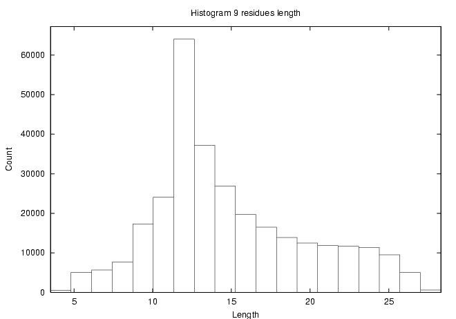 |
|
(January 2002)
Clipper - a set of object-oriented libraries for the organisation of crystallographic data and the performance of crystallographic computation.
(January 2002)
SHARP/autoSHARP
autoSHARP: a fully automated structure solution system - from merged data to automatic model building (uses SHARP as phasing engine).
(January 2002)
I am at the end of refinement of my structure. Things went great.
Then now that my R-factors are 15.5 and Rfree is 17.0 (data to 1.1Å
resolution) refined with anisotropic b factors, I am suddenly getting:
Problem in MAKE_U_POSITIVE -0.1387620
How do I find out the offending atom(s) - or did something else go crazy.
The geometry are all well behaved. I have 8 Zn+2 in my structure and
their equivalent isotropic B's are positive.....
Run the output PDB file through the PARVATI web server for analysis of the anisotropic refinement, a list of problematic atoms, and mug shots of offending residues:
PARVATI - Protein Anisotropic Refinement Validation and Analysis Tool
(February, March, April 2002)
povscript+ - a modified version of molscript and its complementary povray patch povscript.
(February 2002)
MAPMAN server - will run the program MAPMAN on your ASCII electron-density map or mask to generate an O-style map.
(March 2002)
Reprint Mailer
(April 2002)
pdb-mode is a mode for the GNU-Emacs/XEmacs editors, providing editing functions of relevance to Protein DataBank (PDB) formatted files. This includes simple ways of selecting groups of atoms and changing attributes such as B-factor, occupancy, residue number, chain ID, SEGID etc.
New features include the abilities to ...... all within the comfort of your editor, (X)Emacs.
- Insert new sequence
- Mutate residues
- Insert HETGROUPS directly from HICUP
- Directly submit coordinates to PRODRG server
- Interconvert fractional and orthogonal coordinates
See Charlie Bond - Publications for more info and downloads.
(March, May 2002)
MOSFLM help and guidance
(March, 2002)
Electron Density Server
(March, 2002)
Then a recipe for 'how to obtain the topology and parameter files for acarbose for the CNS suite', combining PRODRG and HIC-Up:
- go to HIC-Up
- click on "Search HIC-Up"
- enter "acarbose" in the Google search box and click the search button
- this gives four hits (ACR, ABD, ABC, GAC); select the one that you want and click on the corresponding link
- this gives you the HIC-Up page for your compound with loads of information and links
- to run the PRODRG server on your acarbose compound, scroll down and hit "Run PRODRG"
- in many cases, the PDB file you get out of PRODRG will have more sensible geometry than the one found in the PDB; save it in a file
- select the "HIC-Up server" and upload the new coordinate file to get CNS, O, etc dictionaries calculated using the new coordinates
- you need dictionaries for a hetero compound
(June 2002)
Raster3D - a set of tools for generating high quality raster images of proteins or other molecules.
(June 2002)
'ccp4get' CCP4 version 4.2.1 for Linux binary installer
(June 2002)
** Announcement of New Services to the PDB **
- Secondary Structure Matching
a tool for protein structure comparison
URL : http://www.ebi.ac.uk/msd-srv/ssm
Author: Eugene Krissinel <keb@ebi.ac.uk>
This is an interactive service for comparing protein structures in 3D
based on a new algorithm for common subgraph isomorphism- Hetgroup interface for accessing the ligands and small molecule
dictionary of compounds found in the PDB
URL: http://www.ebi.ac.uk/msd-srv/chempdb
Author: Dimitris Dimitropoulos <dimitris@ebi.ac.uk>
An interface to an MSD reference data warehouse containing a
consistent and enriched library of all the small molecules and
monomers that are refered in any macromolecular structure.** As of Wednesday Jun 19 2002 the following EBI/MSD services were moved from an SGI server to a SUN server:
http://oca.ebi.ac.uk Integrates data query form for the PDB http://pqs.ebi.ac.uk Protein Quaternary Structure Query Form http://autodep.ebi.ac.uk PDB deposition form http://capri.ebi.ac.uk Home page for protein-protein docking for structure prediction http://iims.ebi.ac.uk Some aspects of Electron Microscopy data model (Home Page: http://www.ebi.ac.uk/msd/MSDProjects/IIMShome.html) We would welcome feedback to msd@ebi.ac.uk on any problems user may encounter during this change over period. This weeks PDB update is the first under the new operating system.
Also note that
- the service http://relibase.ebi.ac.uk/ from 1-July-2002 will be temporarily directed to http://relibase.ccdc.cam.ac.uk/ until a linux version is re-instated at the EBI.
- the service http://www.ebi.ac.uk:80/dali/ is in the process of a port from SGI to Linux and will be maintained after 1-July-2002 by the MSD group.
(July 2002)
ARP/wARP
(July 2002)
HIC-Up
(July 2002)
Reminder X-ray generators can bite, especially if you qualify for the LFH Club for Scientists™.
(September 2002)
PyMOL
(Here and now)
AMoRe webpage